Multi-function vacuum cleaner

A vacuum cleaner, multi-functional technology, applied in the direction of vacuum cleaners, suction nozzles, exhaust diffusers, etc., can solve the problems of dust shock overflow, unfavorable hygiene quality, dust overflow, etc., to avoid mutual collision damage, scientific and reasonable structure, and avoid shock overflow effect

Inactive Publication Date: 2018-11-30
李成锦
View PDF0 Cites 2 Cited by
  • Summary
  • Abstract
  • Description
  • Claims
  • Application Information

AI Technical Summary

Problems solved by technology

[0003] The present invention provides a multi-functional vacuum cleaner, which can effectively solve the problem mentioned in the background art that when cleaning in a dark environment, it is difficult to effectively find the stubborn stains on the smooth ground, resulting in a decrease in the cleanliness of the vacuum cleaner, which is not conducive to ensuring a high indoor environment. At the same time, when it is found that stubborn stains are attached to the ground, it is difficult for the existing vacuum cleaner to clean the stubborn adsorbed stains. It is necessary to use mops and other tools to deal with them after vacuuming, which increases the labor intensity of users for indoor cleaning. , in the process of vacuuming, it is necessary to move the vacuum cleaner to avoid the detachment of the connecting pipe and the suction rod, which greatly increases the possibility of the separation of the connecting pipe and the suction rod, which is easy to cause dust overflow. Pushing or moving the vacuum cleaner also increases the labor intensity of the user. The survival and reproduction of bacteria and germs are prone to occur on the ground. Residues are not conducive to improving the indoor hygiene quality. When the vacuum cleaner is moving, it is subjected to large lateral vibrations, which may easily cause the dust loaded inside to vibrate and overflow, and may also easily cause the internal mechanisms of the vacuum cleaner to collide and damage each other.

Method used


Image

  • Multi-function vacuum cleaner
  • Multi-function vacuum cleaner
  • Multi-function vacuum cleaner

Examples


Embodiment

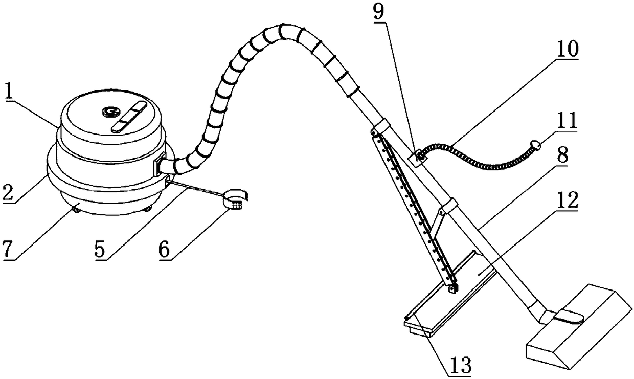
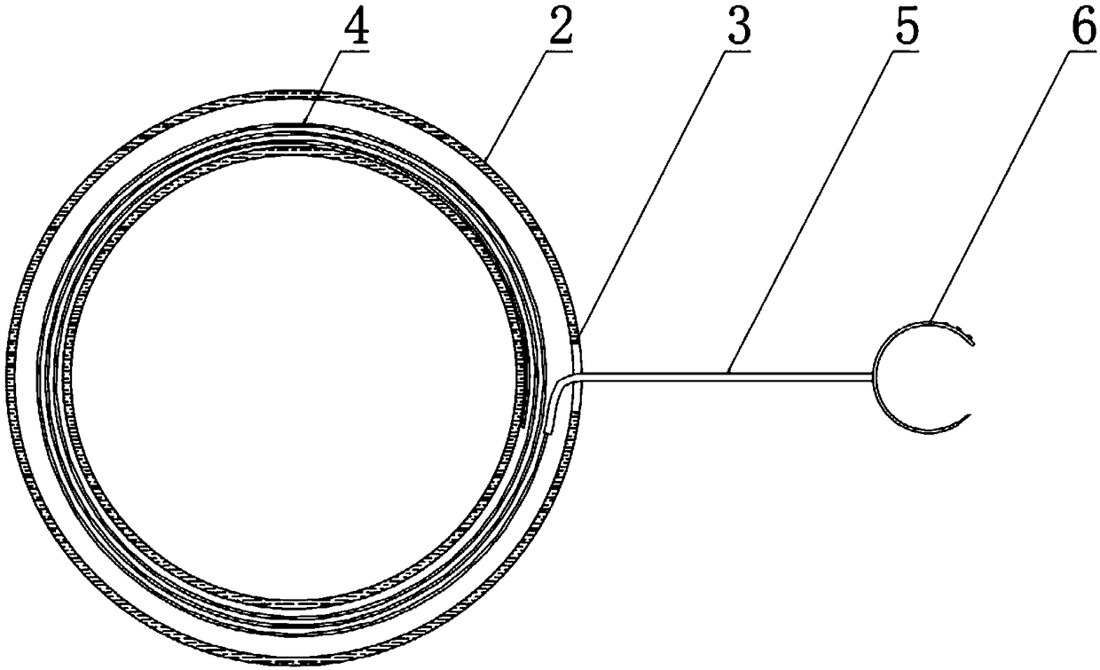
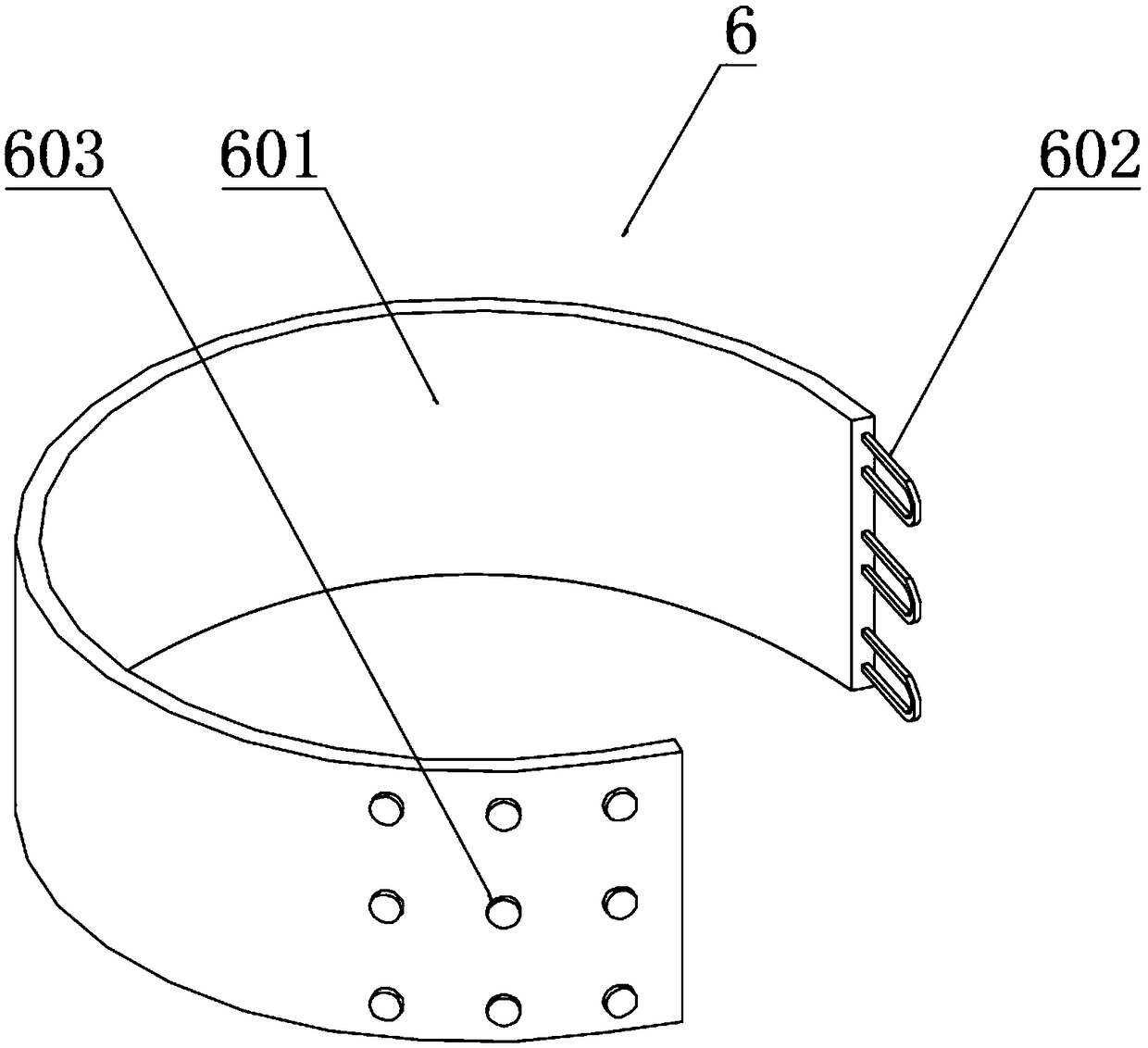
[0026] Example: such as Figure 1-6 As shown, the present invention provides a technical solution, a multifunctional vacuum cleaner, including a vacuum cleaner housing 1, a storage shell 2 is welded on the outer side of the bottom of the vacuum cleaner shell 1, a rope outlet 3 is opened on one side of the storage shell 2, and the storage shell 2 A plane scroll spring 4 is installed inside, a traction rope 5 is installed at one end of the plane scroll spring 4, and a bolting mechanism 6 is installed at one end of the traction rope 5, and the bolting mechanism 6 includes a bolting cloth 601, a rope buckle 602 and a buckle 603, One end of the tie cloth 601 is sewn with a rope buckle 602, and the other end of the tie cloth 601 is sewn with buckles 603. In order to facilitate the adjustment of the length of the tie cloth 601 and the stability after the tie, the buckle 603 is arranged in three rows , the number of each row is set to three, and the tie cloth 601 and the traction rope...


PUM


Abstract

The invention discloses a multi-function vacuum cleaner which comprises a vacuum cleaner housing; a receiving outer case is welded to the outer side of the bottom of the vacuum cleaner housing, and adust suction rod is mounted on one side of the vacuum cleaner housing; a mopping mechanism is installed below the middle portion of the dust suction rod. The structure of the invention is scientific and reasonable, and the use is safe and convenient. A damper spring that is sleeved on the outside of a damper column effectively reduces the lateral movement of the device when it moves horizontally,which avoids the lateral movement causing the shock of the dust inside the vacuum cleaner to overflow, and at the same time avoids the mutual collision damage of the internal components of the vacuumcleaner; the mop is attached to the ground to ensure that the mop can effectively clean the attached stain on the ground when the vacuum cleaner is moving, which solves the problem that the existing vacuum cleaner is difficult to clean the stubborn stain on the ground; UV disinfection lamps can effectively disinfect the cleaned ground, reduce the residual bacteria on the ground, and avoid the damage of the bacteria to the residents.

Description

technical field [0001] The invention relates to the technical field of household appliances, in particular to a multifunctional vacuum cleaner. Background technique [0002] With the rapid development of social economy, people's daily living requirements are gradually increasing. Indoor sanitation cleaning is still one of the ways to improve the quality of people's daily life. In order to reduce the fatigue of users due to cleaning, vacuum cleaners on the market are widely used. In indoor cleaning, the working principle of the vacuum cleaner is to use the motor to drive the blades to rotate at high speed, generate air negative pressure in the sealed housing, and absorb dust. The vacuum cleaner is mainly composed of three parts: dust collection, dust collection, and dust filtration. Commutator motors, centrifugal fans, vacuum cleaners (bags) and vacuum accessories, the power of general vacuum cleaners is 400-1000W or higher, and the power of portable vacuum cleaners is genera...

Claims


Application Information

Patent Timeline
Patent Type & Authority Applications(China)
IPC IPC(8): A47L5/00A47L7/00A47L9/00A47L9/02A47L9/30
CPCA47L5/00A47L7/0061A47L9/00A47L9/0081A47L9/02A47L9/30
Inventor 李成锦
Owner 李成锦
Why Eureka
Try Eureka