Non-uniform arrangement carnassial tooth fixed rotor permanent magnet vernier motor

A vernier motor, non-uniform technology, applied to synchronous motors with stationary armatures and rotating magnets, magnetic circuits, electric components, etc., can solve the problems of being unsuitable for ultra-low speed operation and increasing the magnetic density of the air gap, and achieve low Effects of torque ripple, high torque density, and suppression of cogging torque ripple

Inactive Publication Date: 2018-11-27
无锡力必特自动化设备有限公司
View PDF14 Cites 24 Cited by
  • Summary
  • Abstract
  • Description
  • Claims
  • Application Information

AI Technical Summary

Benefits of technology

This innovative technology improves the performance of electric machines by reducing noise caused during rotation due to gear meshing between different parts or components. It also reduces vibrations when operating at lower speeds compared to traditional designs while maintaining stability. Additionally, it combines these benefits into one device design without adding extra hardware like bearings or seals.

Problems solved by technology

This patented technology describes various improvements made over previous designs involving improving the performance of certain types of servo drives called PWM Direct Dual Flux Drive ("PDD") Verniers Motor," including improved power conversion capabilities through better control techniques like pulse width modulated current injection("SPM"), increased space factorization, higher speeds, lower rotation rates, greater flexibility without increasing weight or size compared to conventional arrangements. Additionally, this new type of solution involves eliminating the need for expensive rare earth materials while maintaining good electrical properties.

Method used


Image

  • Non-uniform arrangement carnassial tooth fixed rotor permanent magnet vernier motor
  • Non-uniform arrangement carnassial tooth fixed rotor permanent magnet vernier motor
  • Non-uniform arrangement carnassial tooth fixed rotor permanent magnet vernier motor

Examples


Embodiment Construction

[0034] In order to make the technical means, creative features, goals and effects achieved by the present invention easy to understand, the present invention will be further described below in conjunction with specific embodiments.

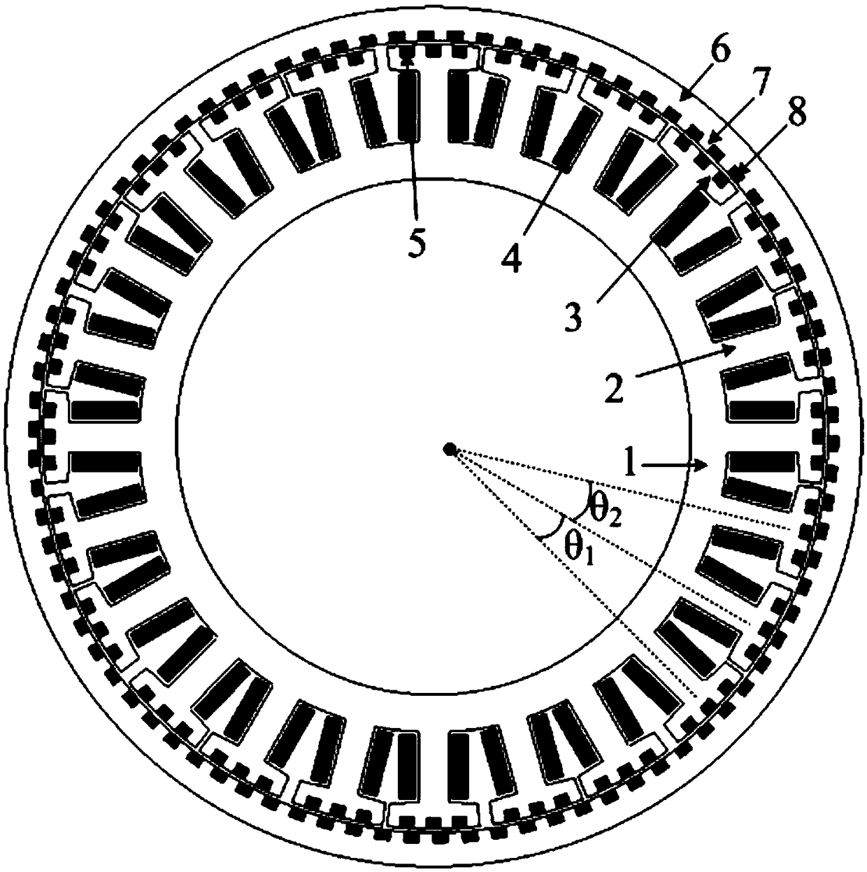
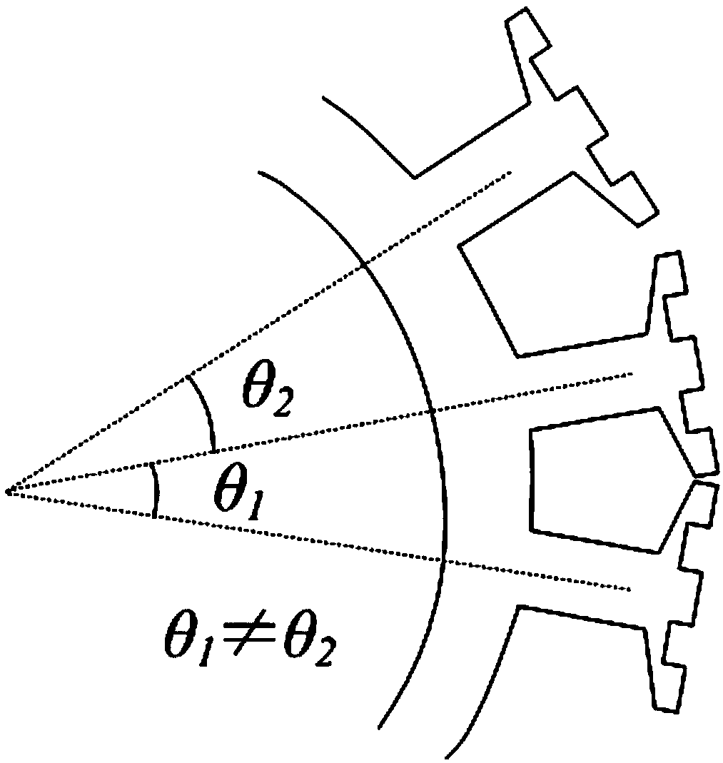
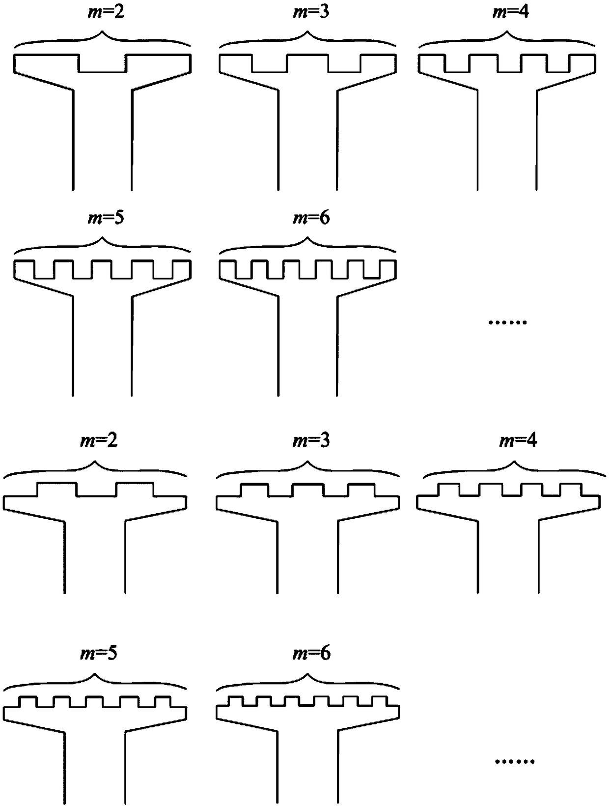
[0035] refer to Figure 1-10, the specific embodiment adopts the following technical scheme: a non-uniformly arranged split-tooth stator-rotor permanent magnet vernier motor, including a stator and a rotor component, the stator includes a stator yoke 1, a stator large tooth 2, a stator split tooth 3, a winding 4 and stator permanent magnet 5, the rotor includes rotor yoke 6, rotor tooth 7 and rotor permanent magnet 8, the stator large teeth 2 connected with stator yoke 1 are arranged non-uniformly in space, and the stator large teeth 2 split into stator cracks at the end tooth 3, the stator permanent magnet 5 is placed in the slot formed by the stator split tooth 3, the winding 4 is placed in the slot formed by the stator large tooth 2, the rotor ...


PUM


Abstract

The invention discloses a non-uniform arrangement carnassial tooth fixed rotor permanent magnet vernier motor, and relates to the technical field of a permanent magnet direct driving motor. The motorcomprises components such as a stator and a rotor, wherein the stator comprises a stator yoke, a stator big tooth, stator carnassial teeth, a winding and a stator permanent magnet; the rotor comprisesa rotor yoke, a rotor tooth and a rotor permanent magnet; the stator big teeth connected with the stator yoke are in non-uniform arrangement on the space; the stator big tooth is split into stator carnassial tooth at the tail end; the stator permanent magnet is put in a groove formed by the stator carnassial tooth; the winding is put into a groove formed by the big tooth; the rotor permanent magnet is put into a groove formed by the rotor tooth. The limitation on the permanent magnet motor winding group pole pair number and the rotor pole pair number is solved, so that the motor is suitable for ultra-low-speed operation; the tooth harmonic torque is weakened, so that the motor operation is stable; the air gap magnetic density is improved, so that the torque density is increased by the motor. The motor is applicable to occasions of direct driving machine tool rotating table, a robot joint and the like. The speed reducing machine can be replaced; the market application prospects are wide.

Description


Claims


Application Information

Patent Timeline
Owner 无锡力必特自动化设备有限公司
Why Eureka
Try Eureka