
Three-dimensional geometry and eigencomponent reconstruction method and device based on light and shadow optimization

A three-dimensional geometry and composition technology, applied in the field of computer vision, can solve problems such as slow speed, expensive fraud, and error in scanning results, and achieves broad application prospects, low equipment requirements, and accurate solutions.

Inactive Publication Date: 2018-11-27
TSINGHUA UNIV
View PDF1 Cites 11 Cited by
  • Summary
  • Abstract
  • Description
  • Claims
  • Application Information

AI Technical Summary

Problems solved by technology

However, the acquisition of high-quality 3D models is usually achieved by expensive laser scanners or multi-camera array systems. Although the accuracy is high, there are also some obvious disadvantages: first, the object is required to remain absolutely still during the scanning process, and the tiny Moving will lead to obvious errors in the scanning results; second, counterfeiting is expensive, and it is difficult to popularize it in the daily life of ordinary people. It is often used in large companies or national statistics departments
Third, the speed is slow. It often takes at least 10 minutes to several hours to rebuild a 3D model, and the cost of rebuilding a dynamic model sequence is even greater.
But this reconstruction method needs to obtain the key frame 3D model of the object in advance
On the other hand, although the existing frame-by-frame dynamic fusion surface reconstruction methods can achieve dynamic 3D reconstruction without templates, they only use non-rigid surface deformation methods, and the robustness of tracking reconstruction is low.

Method used


Image

  • Three-dimensional geometry and eigencomponent reconstruction method and device based on light and shadow optimization
  • Three-dimensional geometry and eigencomponent reconstruction method and device based on light and shadow optimization
  • Three-dimensional geometry and eigencomponent reconstruction method and device based on light and shadow optimization

Examples


Embodiment Construction

[0051] Embodiments of the present invention are described in detail below, and examples of the embodiments are shown in the drawings, wherein the same or similar reference numerals denote the same or similar elements or elements having the same or similar functions throughout. The embodiments described below by referring to the figures are exemplary and are intended to explain the present invention and should not be construed as limiting the present invention.

[0052] The method and method for reconstructing 3D geometry and intrinsic components based on light and shadow optimization according to the embodiments of the present invention will be described below with reference to the accompanying drawings. rebuild method.

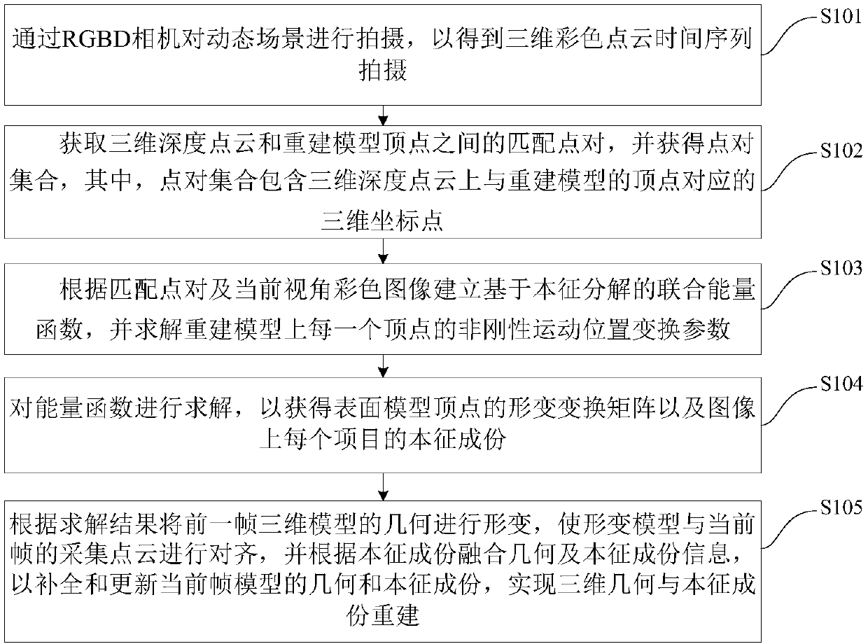
[0053] figure 1 It is a flowchart of a method for reconstructing 3D geometry and intrinsic components based on light and shadow optimization according to an embodiment of the present invention.

[0054] Such as figure 1 As shown, the 3D geometry and eigenc...


PUM


Abstract

The invention discloses a three-dimensional geometry and eigencomponent reconstruction method and device based on light and shadow optimization. The method comprises the following steps of: obtainingthree-dimensional color point cloud time series shooting by an RGBD camera; obtaining matching point pairs between a three-dimensional depth point cloud and vertexes of a reconstructed model, and obtaining a point pair set; establishing a joint energy function based on eigendecomposition according to the matching point pairs and a current view angle color image, and solving non-rigid motion position transformation parameters of each vertex on the reconstruction model; solving the energy function to obtain a deformation transformation matrix of vertexes of a surface model and eigencomponents ofeach item on the image; deforming the geometry of the previous frame three-dimensional model according to the solution result, complementing and updating the geometry and eigencomponents of the current frame model, and realizing three-dimensional geometry and eigencomponent reconstruction. The method can improve the track deformation robustness of a dynamic object in a sparse and single viewpointcondition, can obtain accurate solution, is low in requirement for devices, and has broad application prospect.

Description

technical field [0001] The invention relates to the technical field of computer vision, in particular to a method and device for reconstructing three-dimensional geometry and intrinsic components based on light and shadow optimization. Background technique [0002] 3D reconstruction of dynamic objects is an important issue in the fields of computer graphics and computer vision. High-quality 3D models of dynamic objects, such as human bodies, animals, human faces, and human hands, have broad application prospects and important application values ​​in the fields of film and television entertainment, sports games, and virtual reality. However, the acquisition of high-quality 3D models is usually achieved by expensive laser scanners or multi-camera array systems. Although the accuracy is high, there are also some obvious disadvantages: first, the object is required to remain absolutely still during the scanning process, and the tiny Moving will lead to obvious errors in the sca...

Claims


Application Information

Patent Timeline
Patent Type & Authority Applications(China)
IPC IPC(8): G06T17/00G06T15/50
CPCG06T15/50G06T17/00G06T2210/44
Inventor 刘烨斌戴琼海徐枫
Owner TSINGHUA UNIV
Learn More