
A textile fabric winding device

A winding device and a technology for textile fabrics, which are applied in the direction of winding strips, thin material processing, transportation and packaging, etc., can solve the problems of poor winding effect, etc., and achieve the effect of convenient disassembly

Inactive Publication Date: 2018-11-27
苏州蓝奥纺织科技有限公司
View PDF0 Cites 1 Cited by
  • Summary
  • Abstract
  • Description
  • Claims
  • Application Information

AI Technical Summary

Problems solved by technology

[0004] The object of the present invention is to provide a textile cloth winding device, which has the advantages of good winding effect and solves the problem of poor winding effect of the existing textile cloth winding device

Method used

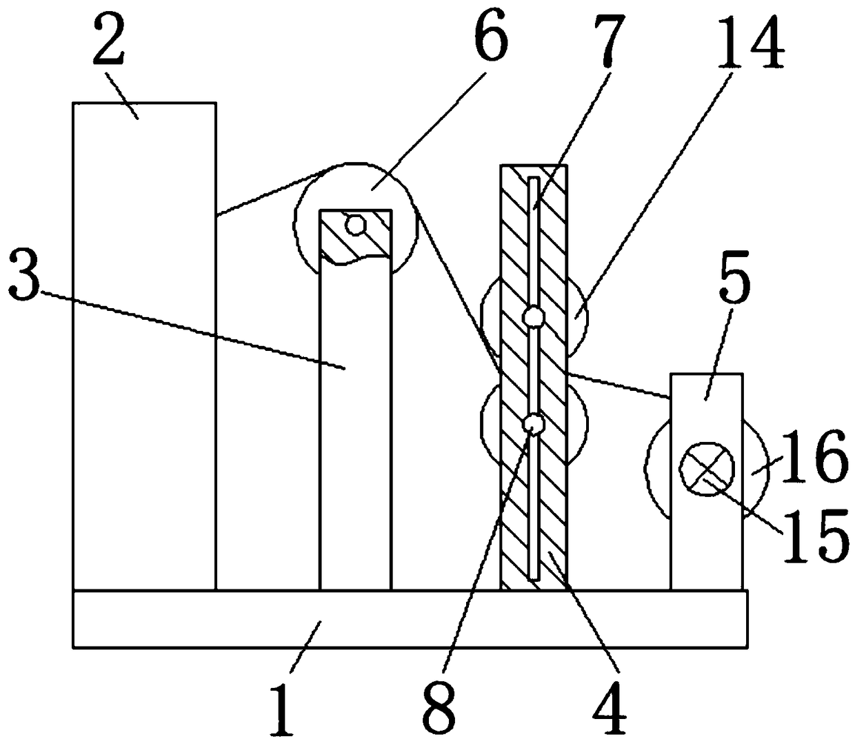

Image

  • A textile fabric winding device
  • A textile fabric winding device
  • A textile fabric winding device

Examples


Embodiment Construction

[0016] The following will clearly and completely describe the technical solutions in the embodiments of the present invention with reference to the accompanying drawings in the embodiments of the present invention. Obviously, the described embodiments are only some, not all, embodiments of the present invention. Based on the embodiments of the present invention, all other embodiments obtained by persons of ordinary skill in the art without making creative efforts belong to the protection scope of the present invention.

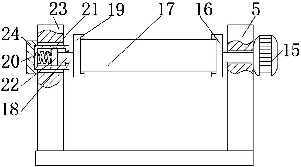
[0017] see Figure 1-3 , a textile cloth winding device comprising a bottom plate 1, the top of the bottom plate 1 is respectively fixedly connected with a spinning machine 2, a first support rod 3, a second support rod 4 and a third support rod 5, and the third support rod 5 is The top of the surface is provided with a first through hole, which is used in conjunction with the output end of the motor 15. The first through hole facilitates the movement of the o...


PUM


Abstract

A take-up device for textile cloth Including bottom plate, the top of the bottom plate is fixedly connected with a spinning machine, a first support bar, a second support bar and a third support bar,wherein the rear side of the top of the first support bar is movably connected with a first roller through a first shaft pin, the front surface of the second support bar is provided with a vertical groove, and the top and bottom of the front surface of the vertical groove are movably connected with a finite ring. As that bottom plate is arrange, Cloth spinning machine, first support bar, second support bar, Third support bar, The first roller, the vertical groove, the limiting ring, the second axle pin, the first slider, the second slider, the connecting block, the telescopic rod, the second roller, the motor, the first positioning housing, the third roller, the movable rod, the second positioning housing, the positioning box, the spring, the third slider, the fourth support rod and the bearing seat are used together, and the problem of poor winding effect of the existing textile fabric winding device is solved at the same time.

Description

technical field [0001] The invention relates to the technical field of textile machine equipment, in particular to a textile cloth winding device. Background technique [0002] Textile machines, also known as spinning machines, looms, cotton spinning machines, etc., early looms were looms driven by manpower. Many new shuttleless looms have been put into the market one after another. The efficiency of the loom has achieved remarkable results, and it has been widely used in countries all over the world, and the process of weaving equipment transformation has been accelerated. In many developed countries, the share of shuttleless looms has reached about 80%. The big trend of shuttle looms. [0003] With the rapid development of the textile industry, the textile machine is also constantly improving with the development of the textile industry. The existing textile machine includes a textile cloth winding device, and the existing textile cloth winding device has a poor effect of...

Claims


Application Information

Patent Timeline
Patent Type & Authority Applications(China)
IPC IPC(8): B65H23/26
CPCB65H23/26B65H2404/15B65H2404/17
Inventor 葛静
Owner 苏州蓝奥纺织科技有限公司
Learn More