A heat sink for microelectronic components

A technology for microelectronic components and heat sinks, applied in electrical components, structural parts of electrical equipment, cooling/ventilation/heating renovation, etc. Simple, to achieve the effect of water circulation

Active Publication Date: 2019-12-06
安徽干城电子科技有限公司
View PDF3 Cites 0 Cited by
  • Summary
  • Abstract
  • Description
  • Claims
  • Application Information

AI Technical Summary

Problems solved by technology

[0002] With the rapid development of the electronic industry today, electrical appliances and various equipment have entered people's production and life. However, with the use of electronic equipment, solving the problem of heat generated by electronic equipment has always troubled many people. The heat generated inside electrical appliances is extremely high. It is easy to cause damage to electronic components, and even cause problems such as fire
[0003] At present, most of the heat dissipation devices on the market basically use cooling fans to dissipate heat, but the effect of air cooling is poor, and the effect will be even worse in hot summer. The use of air cooling and heat dissipation cannot completely achieve heat dissipation for electrical appliances, so we propose A cooling device for microelectronic components used to solve the above-mentioned problems

Method used


Image

  • A heat sink for microelectronic components
  • A heat sink for microelectronic components
  • A heat sink for microelectronic components

Examples


Embodiment Construction

[0018] The following will clearly and completely describe the technical solutions in the embodiments of the present invention with reference to the accompanying drawings in the embodiments of the present invention. Obviously, the described embodiments are only some, not all, embodiments of the present invention.

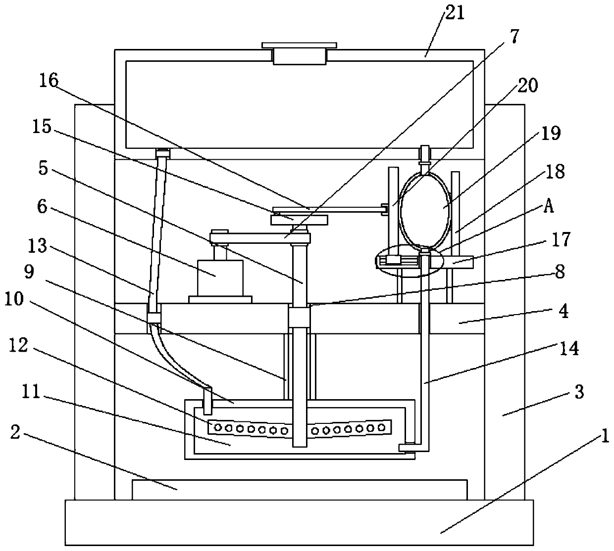
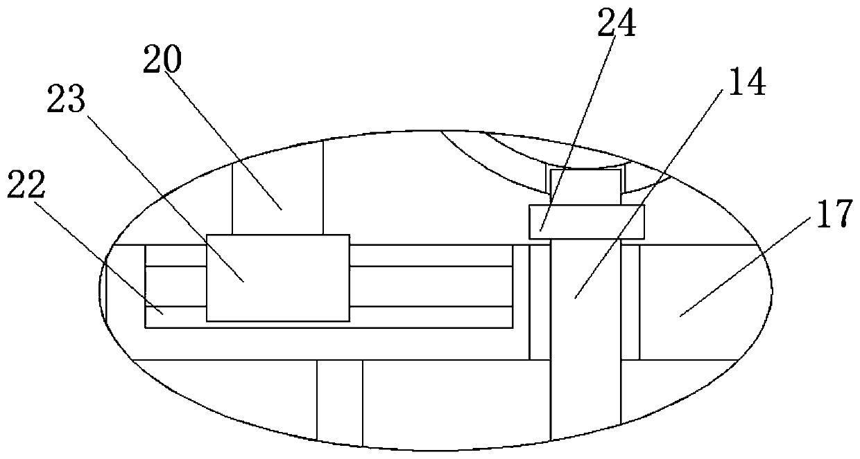
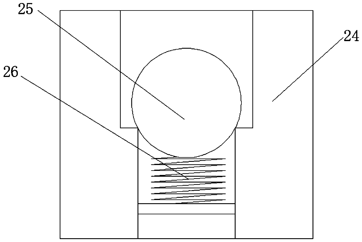
[0019] refer to Figure 1-3 , a cooling device for microelectronic components, comprising a mounting base 1, an electronic component body 2 is fixedly mounted on the top of the mounting base 1, and two columns 3 are symmetrically fixedly mounted on the top of the mounting base 1, and the two columns 3 are respectively located on the electronic component body On both sides of 2, the same installation beam 4 is fixedly installed on the side where the two columns 3 are close to each other. A copper plate 10 is fixedly installed at the end, and a cooling chamber 11 is provided on the copper plate 10. A water inlet pipe 13 is fixedly installed on the inner wall of the top...


PUM


Abstract

The invention discloses a heat dissipation device for a microelectronic component. The heat dissipation device comprises a mounting base, an electronic component body is fixedly mounted at the top ofthe mounting base, and two stand columns are symmetrically and fixedly mounted at the top of the mounting base, and two columns are respectively located on two sides of the electronic component body,the same mounting beam is fixedly mounted on a side where the two columns are close to each other, a rotating shaft is rotationally connected with the mounting beam, a mounting pipe is fixedly mounted at the bottom of the mounting beam, a copper plate is fixedly mounted at a bottom end of the mounting pipe, and a cooling cavity is formed in the copper plate, a water inlet pipe is fixedly installed on an inner wall of one side of the top of the cooling cavity. The heat dissipation device for a microelectronic component has the advantages that operation is simple, by starting a micro motor, a pressure ball can be repeatedly squeezed, and the water flow circulation of the cooling cavity can be realized, so that the electronic component body can be dissipated through the copper plate, and theeffect is better than the heat dissipation fan.

Description

technical field [0001] The invention relates to the technical field of heat dissipation, in particular to a heat dissipation device for microelectronic elements. Background technique [0002] With the rapid development of the electronic industry today, electrical appliances and various equipment have entered people's production and life. However, with the use of electronic equipment, solving the problem of heat generated by electronic equipment has always troubled many people. The heat generated inside electrical appliances is extremely high. It is easy to cause damage to electronic components, and even cause problems such as fire. [0003] At present, most of the heat dissipation devices on the market basically use cooling fans to dissipate heat, but the effect of air cooling is poor, and the effect will be even worse in hot summer. The use of air cooling and heat dissipation cannot completely achieve heat dissipation for electrical appliances, so we propose A cooling devi...

Claims


Application Information

Patent Timeline
Patent Type & Authority Patents(China)
IPC IPC(8): H05K7/20
CPCH05K7/20218
Inventor 吴胜松叶桂如吴胜琴
Owner 安徽干城电子科技有限公司
Why Eureka
Try Eureka