
Display device and shift temporary storage circuit

A technology of shifting temporary storage and shifting temporary registers, which is applied in information storage, static memory, static indicators, etc., and can solve problems affecting display image quality, and achieve the effect of improving smearing and improving quality

Active Publication Date: 2018-11-23
HKC CORP LTD
View PDF6 Cites 5 Cited by
  • Summary
  • Abstract
  • Description
  • Claims
  • Application Information

AI Technical Summary

Problems solved by technology

Therefore, for the shift register of the substrate gate drive circuit, it is necessary to be able to output the gate drive signal stably and accurately, so as not to cause noise due to malfunction, thereby affecting the display image quality.

Method used


Image

  • Display device and shift temporary storage circuit
  • Display device and shift temporary storage circuit
  • Display device and shift temporary storage circuit

Examples


Embodiment Construction

[0040] Specific circuit structural and functional details disclosed herein are representative only and are for purposes of describing example embodiments of the present application. This application may be embodied in many alternate forms and should not be construed as limited to only the embodiments set forth herein.

[0041] In the description of the present application, it is to be understood that the terms "vertical", "transverse", "upper", "lower", "left", "right", "inner", "outer" etc. indicate an orientation or The positional relationship is based on the orientation or positional relationship shown in the drawings, which is only for the convenience of describing the application and simplifying the description, and does not indicate or imply that the referred device or component must have a specific orientation, be constructed and operated in a specific orientation, Therefore, it should not be construed as limiting the application. In addition, the terms "first" and "se...


PUM


Abstract

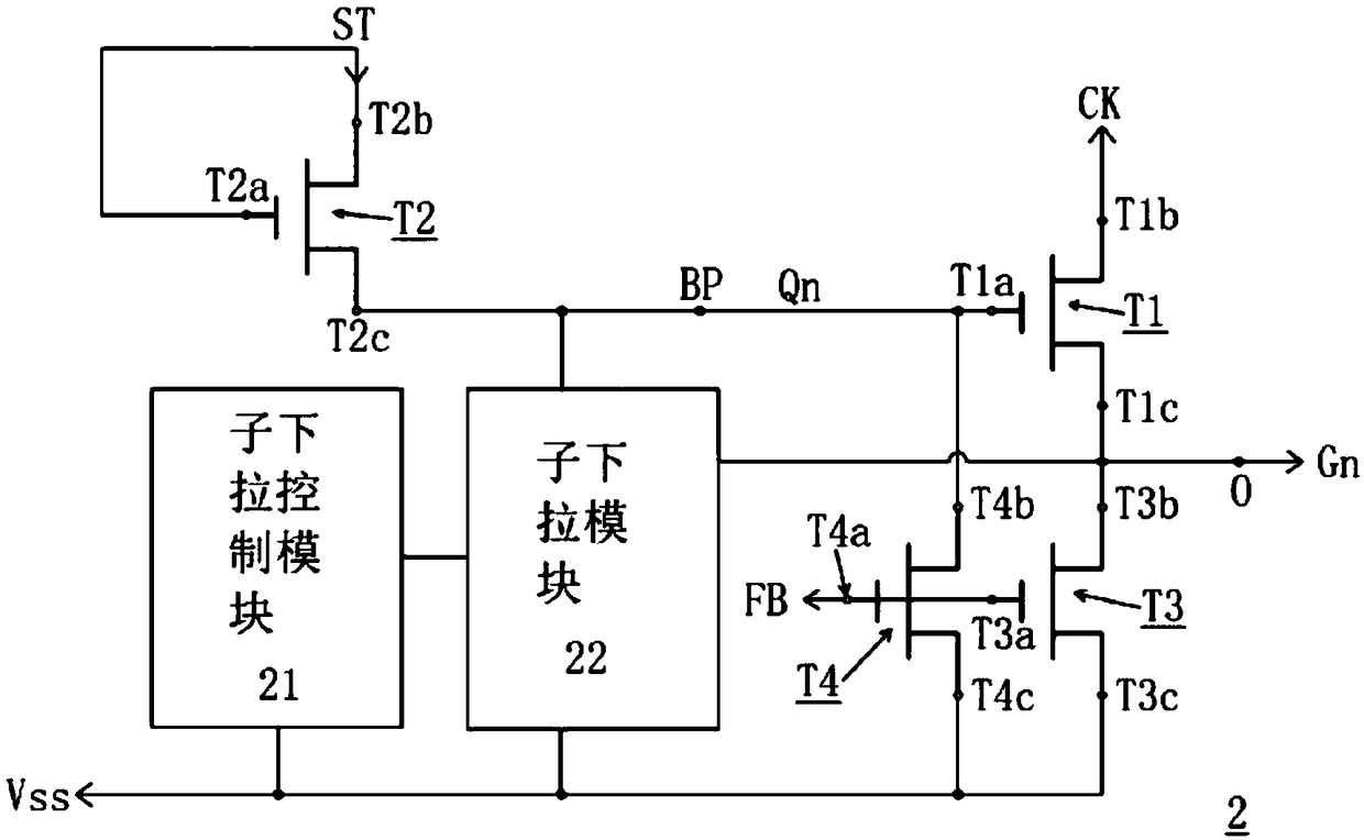
The invention proposes a display device and a shift temporary storage circuit therefor. The shift temporary storage circuit comprises a multistage shift temporary storage unit, wherein one shift temporary storage unit at any stage comprises the following modules: an input module, wherein an input stage transmits a signal to a boost node; a coupling pull-up module which generates a first pull-up signal and pulls the level of the voltage signal to a second level from the first level; an output module which performs the coupling and pulling-up of the level of the voltage signal to the third levelfrom the second level according to a clock signal, and outputs a grid scanning signal through an output end, wherein the coupling pull-up module generates a second pull-up signal when the pulse of the clock signal is finished, and the second pull-up signal acts on the boost node in a coupling manner, so as to enable the voltage signal to remain at the second level; a feedback module which receives a feedback signal, and pulls the level of the voltage signal and the level of the grid scanning signal to a preset low level.

Description

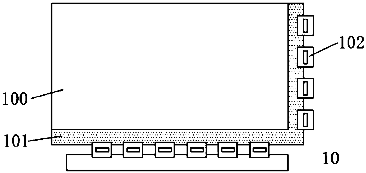
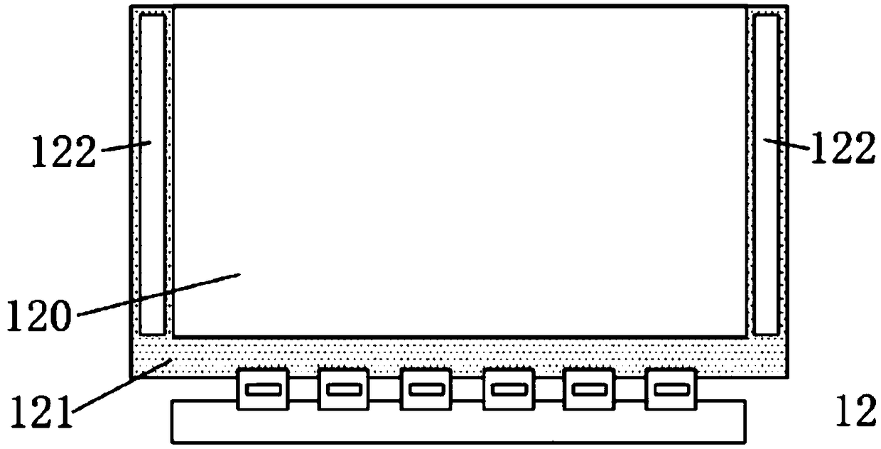
technical field [0001] The present application relates to the technical field of display panels, in particular to a display device with an array substrate gate driving circuit and a shift register circuit thereof. Background technique [0002] In recent years, Liquid Crystal Display (LCD) has been widely used due to its clear and precise image, flat display, thin thickness, light weight, no radiation, low energy consumption, and low operating voltage. When a traditional liquid crystal display performs gate driving, it mainly uses a gate driver chip (Gate Driver 1C) to realize. Since the gate driving chip needs to be connected to the display panel (Panel) through a connector, and multiple gate driving chips need to be used in one liquid crystal display, the manufacturing cost of the liquid crystal display is still relatively high. [0003] With the development of new technologies, many liquid crystal display panels have adopted Gate Driver Array (GOA) technology to replace e...

Claims


Application Information

Patent Timeline
Patent Type & Authority Applications(China)
IPC IPC(8): G09G3/36G09G3/20G11C19/28
CPCG09G3/20G09G3/3677G09G2310/0286G11C19/28
Inventor 单剑锋
Owner HKC CORP LTD
Learn More