A metal non-destructive flaw detection device with electronic display function

A non-destructive detection and electronic display technology, which is applied in the direction of optical testing for flaws/defects, can solve the problems of missed detection, inaccurate detection results, large errors, inaccurate detection results, etc., and achieve the effect of improving detection accuracy

Active Publication Date: 2020-12-04
深圳市钧诚精密制造有限公司
View PDF13 Cites 0 Cited by
  • Summary
  • Abstract
  • Description
  • Claims
  • Application Information

AI Technical Summary

Problems solved by technology

[0003] However, at present, most of the existing flaw detection devices need to be hand-held to complete the detection. There is no mechanical automatic flaw detection equipment. Hand-held flaw detection devices often have the risk of missing detection and inaccurate detection results. The error of flaw detection caused by human operation is relatively large, especially for For those devices that have been exposed to the outdoors for a long time, there are residues on the surface, which will lead to inaccurate detection results

Method used


Image

  • A metal non-destructive flaw detection device with electronic display function
  • A metal non-destructive flaw detection device with electronic display function
  • A metal non-destructive flaw detection device with electronic display function

Examples


Embodiment 1

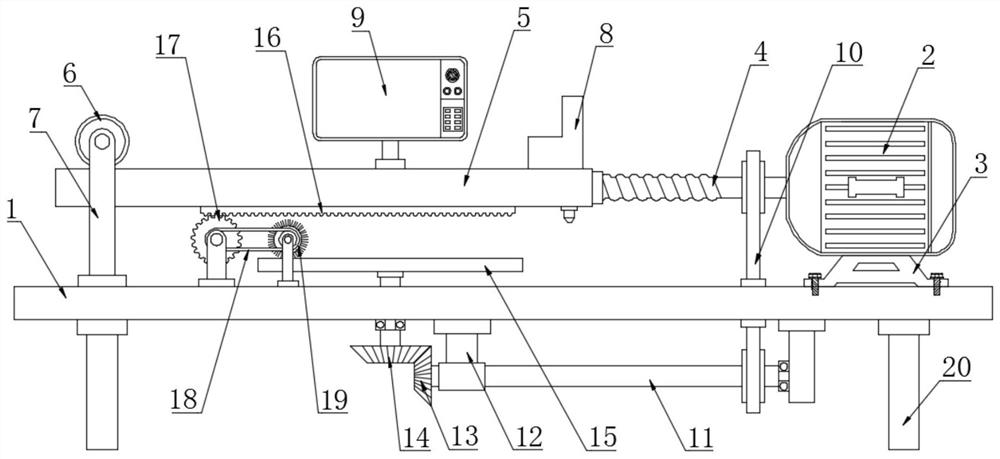
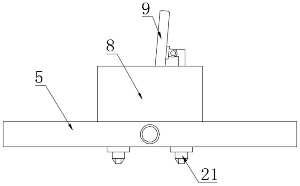
[0020] see Figure 1~3 , in an embodiment of the present invention, a metal non-destructive flaw detection device with electronic display function, comprising a base plate 1, a movable top plate 5 and an infrared detector 8; a servo motor 2 is arranged above the end of the base plate 1, and the servo motor 2 is connected by wires Power supply and switch, the lower part of the servo motor 2 is fixedly connected to the motor base 3, the motor base 3 is fixedly connected to the bottom plate 1 by bolts, the servo motor 2 is rotated and connected to the screw rod 4, and pressing the switch forward makes the servo motor 2 turn on the power to drive the screw rod 4 Rotate in the forward direction, press the switch in the reverse direction to drive the screw rod 4 to reverse; one side of the screw rod 4 is provided with a movable top plate 5, and the middle part of the movable top plate 5 is tapped with a threaded hole, and the screw rod 4 is threadedly connected to the threaded hole i...

Embodiment 2

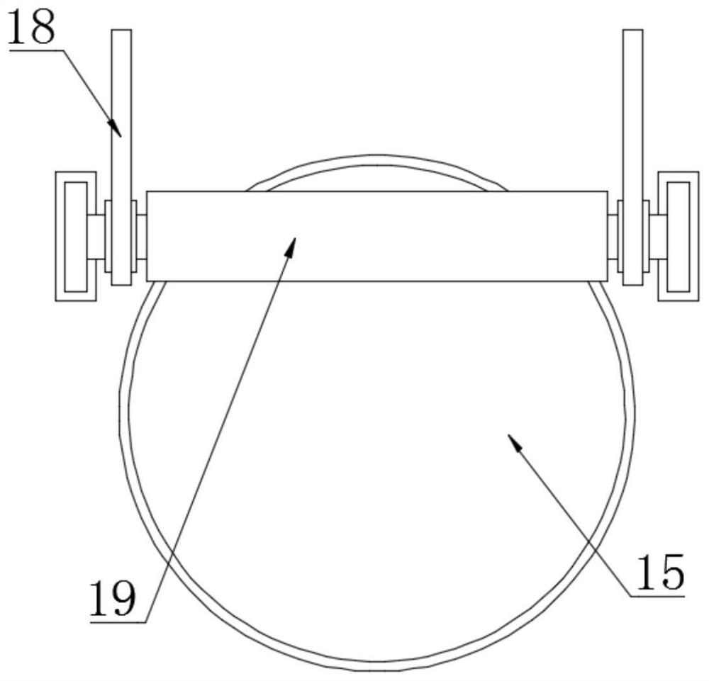
[0023] In order to make the technical solution in this application more abundant and detailed, further supplementary explanations will be made on the basis of the above-mentioned embodiment 1. By adding some technical features, the technical solution of this application will be more complete and substantial, and the disclosure will be more sufficient. , the added part of the technical feature is that the lower surface of the movable top plate 5 is fixedly connected to the rack plate 16, the gear 17 is engaged under the rack plate 16, the gear 17 is connected to the upper part of the bottom plate 1 in rotation, and a brush roller 19 is arranged on one side of the gear 17, The brush roller 19 is rotatably connected to the top of the bottom plate 1, and the brush roller 19 and the gear 17 are connected by a chain 18, wherein the brush roller 19 is located above the worktable 15, and the movable top plate 5 moving left and right drives the rack plate 16 to follow and then drives the...


PUM


Abstract

The invention discloses a metal non-destructive flaw detection device with an electronic display function. A servo motor is arranged above the end part of a bottom plate, and is rotationally connectedwith a screw rod; a movable top plate is arranged on one side of the screw rod, and the screw rod is connected with a threaded hole in the middle of the movable top plate in a threaded mode; a pressing wheel is arranged above the end part of the movable top plate, and is rotationally connected with the upper end of a support rod; a cross beam is fixedly connected to the middle of the support rod;an infrared detector is fixedly connected to the end part of the upper surface of the movable top plate, and two probes are in signal connection below the infrared detector; a stand column is fixedlyconnected to the center of the upper surface of the movable top plate; a display screen is rotationally connected to the stand column, and is in signal connection with the infrared detector. The metal non-destructive flaw detection device has the advantages that the screw rod drives the movable top plate, the infrared detector and the probes to move leftwards and rightwards for flaw detection, the infrared detector displays flaw detection conditions on the display screen to achieve the dynamic display effect, and through a bevel gear set, a driven shaft drives a workbench to rotate to achievethe all-directional detection effect.

Description

technical field [0001] The invention relates to an electronic device, in particular to a metal non-destructive flaw detection device with an electronic display function. Background technique [0002] The detection of cracks or defects inside metal materials or components is a physical flaw detection, and non-destructive flaw detection is performed without chemical changes. Non-destructive testing is to use the sound, light, magnetic and electrical characteristics of the material to detect whether there is a defect or inhomogeneity in the object to be inspected without damaging or affecting the performance of the object to be inspected, and to give the size of the defect. Information such as location, nature and quantity. [0003] However, at present, most of the existing flaw detection devices need to be hand-held to complete the detection. There is no mechanical automatic flaw detection equipment. Hand-held flaw detection devices often have the risk of missing detection an...

Claims


Application Information

Patent Timeline
Patent Type & Authority Patents(China)
IPC IPC(8): G01N21/88
CPCG01N21/88
Inventor 袁园刘朋飞
Owner 深圳市钧诚精密制造有限公司
Why Eureka
Try Eureka