
Building door and window curtain wall wind resistance detection system

A technology for building doors, windows, and detection systems, applied in measuring devices, impact tests, and testing of machine/structural components, etc., can solve problems such as high energy consumption, unutilized wind flow, and inconvenient judgment of the impact of wind speed on doors, windows, and curtain walls. Achieve the effect of convenient adjustment and fixation and energy saving

Inactive Publication Date: 2018-11-23
GUIZHOU ZHENGFANG IND
View PDF9 Cites 5 Cited by
  • Summary
  • Abstract
  • Description
  • Claims
  • Application Information

AI Technical Summary

Problems solved by technology

[0005] The purpose of the present invention is to provide a wind resistance detection system for building doors, windows and curtain walls, to solve the problem of inconvenient adjustment and fixation of building doors, windows and curtain walls by the detection system device in the prior art proposed in the above background technology, and it is inconvenient to judge the influence of wind speed on doors, windows and curtain walls, which cannot be simulated. Under stormy conditions, debris impacts on the wind resistance of building doors and windows. At the same time, during the detection process, the wind flow cannot be used and the energy consumption is high.

Method used


Image

  • Building door and window curtain wall wind resistance detection system
  • Building door and window curtain wall wind resistance detection system
  • Building door and window curtain wall wind resistance detection system

Examples


Embodiment Construction

[0026] The following will clearly and completely describe the technical solutions in the embodiments of the present invention with reference to the accompanying drawings in the embodiments of the present invention. Obviously, the described embodiments are only some, not all, embodiments of the present invention. The specific embodiments described here are only used to explain the present invention, not to limit the present invention. Based on the embodiments of the present invention, all other embodiments obtained by persons of ordinary skill in the art without making creative efforts belong to the protection scope of the present invention.

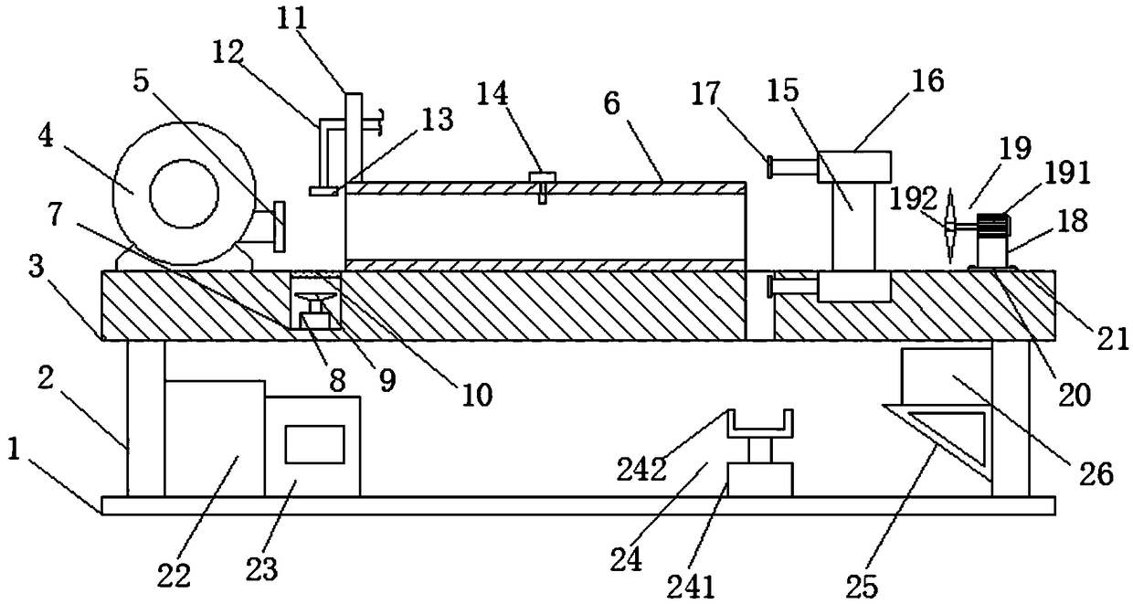
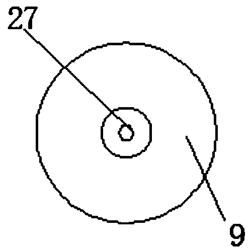
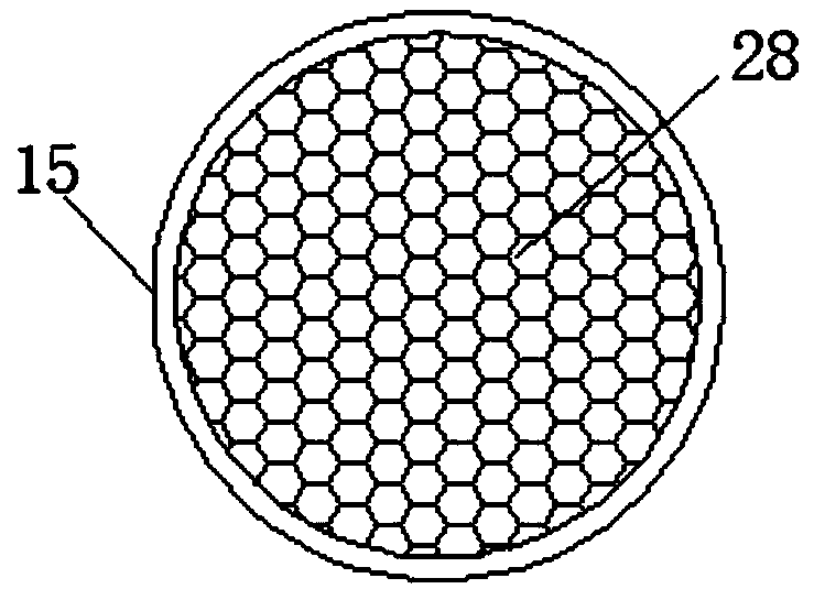
[0027] The present invention provides such Figure 1-5 The wind resistance detection system for building doors, windows and curtain walls shown includes a base 1, a workbench 3 and a leg 2 arranged between the base 1 and the workbench 3, and a blower 4 is installed on the left side of the top of the workbench 3 And the air duct 6, the ai...


PUM


Abstract

The invention discloses a building door and window curtain wall wind resistance detection system comprising a pedestal, a work table, and legs arranged between the pedestal and the work table; a blower and an air duct are arranged on the left side of the work table top; the top of the air duct is provided with a water tube having a nozzle in the end portion; an anemograph is arranged on the bottomin middle of the air duct; two second cylinders are symmetrically arranged up and down on the right side of the air duct on the work table top; through holes are evenly arranged on the bottom of an aggregate groove; the right side of the work table is provided with a wind power generator via the pedestal; a frequency converter and a PLC controller are arranged on the left side of the pedestal; astorage battery is arranged on the leg side of the right side of the pedestal. The system can determine the building door and window curtain wall wind resistance ability under different wind velocitystates, can simulate the impact influences on the building door and window curtain wall by the aggregates under stormy weather conditions, and can utilize the wind blown out by the blower to blow thewind power generator to work, thus saving energy consumption.

Description

technical field [0001] The invention belongs to the technical field of building doors and windows, and in particular relates to a wind resistance detection system for building doors, windows and curtain walls. Background technique [0002] Architecture is the general term for buildings and structures, and it is an artificial environment created by people using the material and technological means they have mastered, and using certain scientific laws, feng shui concepts, and aesthetic principles to meet the needs of social life. Building doors, windows and curtain walls are important basic structures in buildings. [0003] In the process of building door, window and curtain wall processing and production, it is necessary to test the wind resistance performance of the door, window and curtain wall. The traditional detection system device is inconvenient to adjust and fix the building door, window and curtain wall, and it is inconvenient to judge the influence of wind speed on ...

Claims


Application Information

Patent Timeline
Patent Type & Authority Applications(China)
IPC IPC(8): G01M99/00G01M7/08
CPCG01M7/08G01M99/00
Inventor 兰定国
Owner GUIZHOU ZHENGFANG IND
Learn More