Bracket and bracket assembly

An assembly and support technology, applied in the direction of pipe supports, pipe components, vehicle parts, etc., can solve the problems of limited manufacturing methods, expensive and heavy support components, and achieve the effects of firm retention, simple design, and simplified manufacturing process.

Active Publication Date: 2018-11-23
AKWEL SWEDEN AB
View PDF5 Cites 2 Cited by
  • Summary
  • Abstract
  • Description
  • Claims
  • Application Information

AI Technical Summary

Problems solved by technology

[0004] However, the resulting bracket assembly can be relatively expensive and bulky due to the need for additional fixtures, which is disadvantageous
Furthermore, the fabrication method is limited by some scaffold designs and is often not amenable to full automation

Method used


Image

  • Bracket and bracket assembly
  • Bracket and bracket assembly
  • Bracket and bracket assembly

Examples


Embodiment Construction

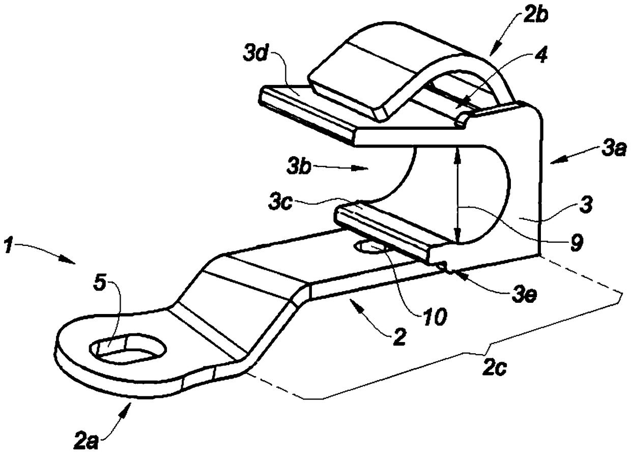
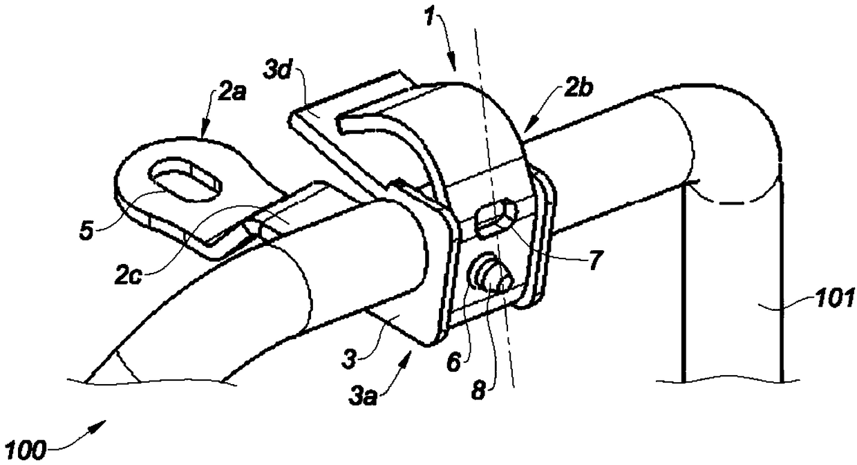
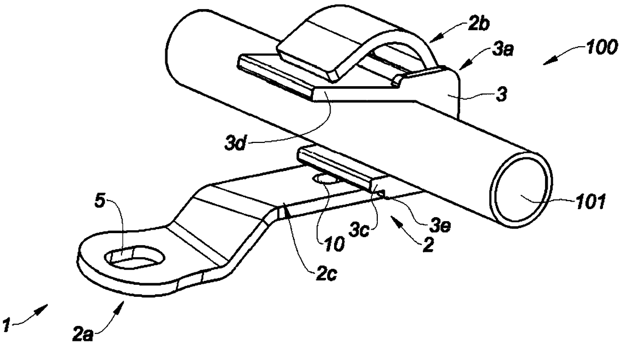
[0077] The stent 1 of the present invention is configured by means of a forming tool 200 to be closed around a pipe element 101 to form a stent assembly 100 . The stent 1 comprises at least one body 2, preferably as figure 1 The metal body shown in 2. The body 2 comprises a first end 2a configured to be fastened to a support, not shown, such as the chassis and engine of a vehicle, preferably a motor vehicle. like figure 1 As shown, the first end 2a includes a fastening interface, such as a fastening hole 5 . The body 2 also includes a second end 2b opposite the first end 2a. The second end 2b is bent to form a bent recess 4 towards the first end 2a and facing the middle portion 2c of the body 2 arranged between the first end 2a and the second end 2b. like figure 2 As shown, the second end 2b includes a positioning opening 7 configured to define the final closed flexed position of the stent 1 .

[0078] like Figures 1 to 3 As shown, the bracket 1 comprises a resilient ...


PUM


Abstract

The invention relates to a bracket (1) intended to be fastened to a support, such as a chassis or an engine of a vehicle, preferably a motor vehicle, the bracket (1) having at least a body (2) including: a first end (2a) configured to be fastened to a support, a second end (2b) opposite to the first end (2a), an intermediate portion (2c) arranged between the first end (2a) and the second end (2b),the second end (2b) being bent so as to form a recess (4) oriented toward the first end and facing the intermediate portion (2c), wherein the bracket (1) further includes an elastic insert arranged in the recess (4) of the second end (2b).

Description

technical field [0001] The invention relates to a stent, a stent assembly comprising at least one stent and a conduit element, and a manufacturing method for preparing said stent assembly. Background technique [0002] Bracket assemblies are widely used to secure plumbing elements, such as pipes, to various supports. Well-known examples of use include securing the tube to the engine or chassis of a vehicle. Typically, the support assembly comprises on the one hand a pipe element comprising at least a pipe section surrounded by an elastomer sleeve and on the other hand a support made of metal strips which surround and clamp the pipe element. [0003] Clamping of the tubing element within the stent is generally accomplished by shaping the stent into a curved U-shape so as to form a generally cylindrical recess between two exposed branches, and then unfolding the legs to insert the tubing element into the recess , and finally press and fasten one branch against the other usin...

Claims


Application Information

Patent Timeline
Patent Type & Authority Applications(China)
IPC IPC(8): F16L3/12B21D39/00
CPCB21D39/00F16L3/12B60R16/0215F16L3/1233F16L55/035B21D7/06B60R16/08
Inventor 马林·帕斯森简·奥洛夫松维克托·罗森
Owner AKWEL SWEDEN AB
Why Eureka
Try Eureka