Movable type rectangular rack pulling type valve mechanism for large-particle solid circulation

A large particle, solid flow technology

Inactive Publication Date: 2018-11-23
DONGGUAN LIANZHOU INTPROP OPERATION MANAGEMENT CO LTD
View PDF4 Cites 0 Cited by
  • Summary
  • Abstract
  • Description
  • Claims
  • Application Information

AI Technical Summary

Problems solved by technology

[0002] Existing valves for liquid flow control generally use circular hole structures for delivery, and valves for some solid particle delivery generally use rectangular hole structures, which are simple to manufacture, low in cost, and low in sealing requirements. There is no such valve at present;
[0003] At the same time, the use of existing valves requires screw connection and fixing, etc., which are generally used for a long time, and are not suitable for detachable connection structures for temporary use, which cannot meet the use of some flexible conveying mechanisms.
[0004] Moreover, the existing valves generally use screw-type rotation or handle rotation to achieve adjustment, and the effect of handle adjustment is not ideal, and the control accuracy is not high, and the screw-type is not suitable for butterfly valve-type adjustment structures.

Method used


Image

  • Movable type rectangular rack pulling type valve mechanism for large-particle solid circulation
  • Movable type rectangular rack pulling type valve mechanism for large-particle solid circulation
  • Movable type rectangular rack pulling type valve mechanism for large-particle solid circulation

Examples


Embodiment Construction

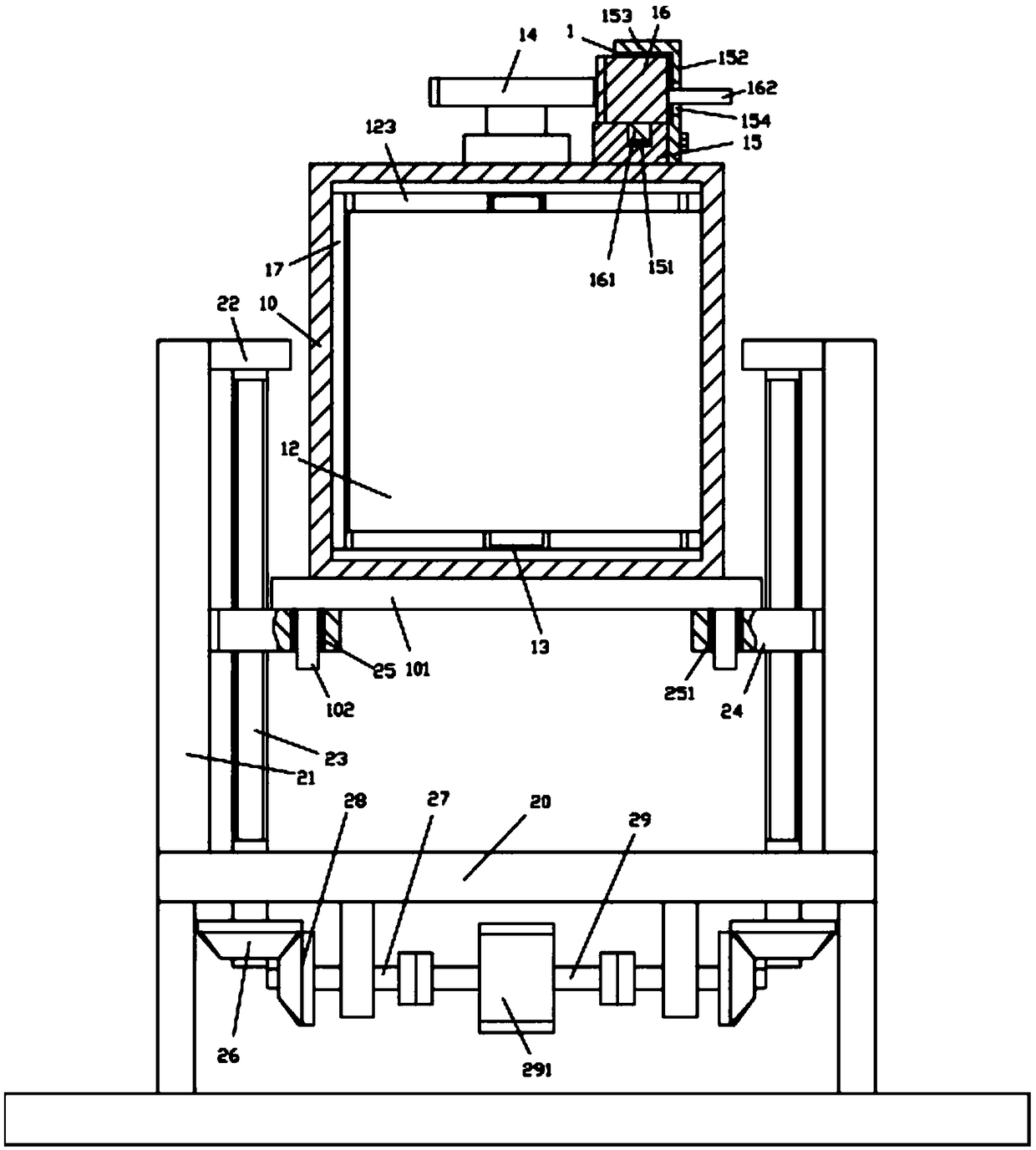
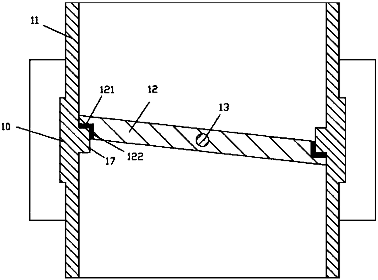
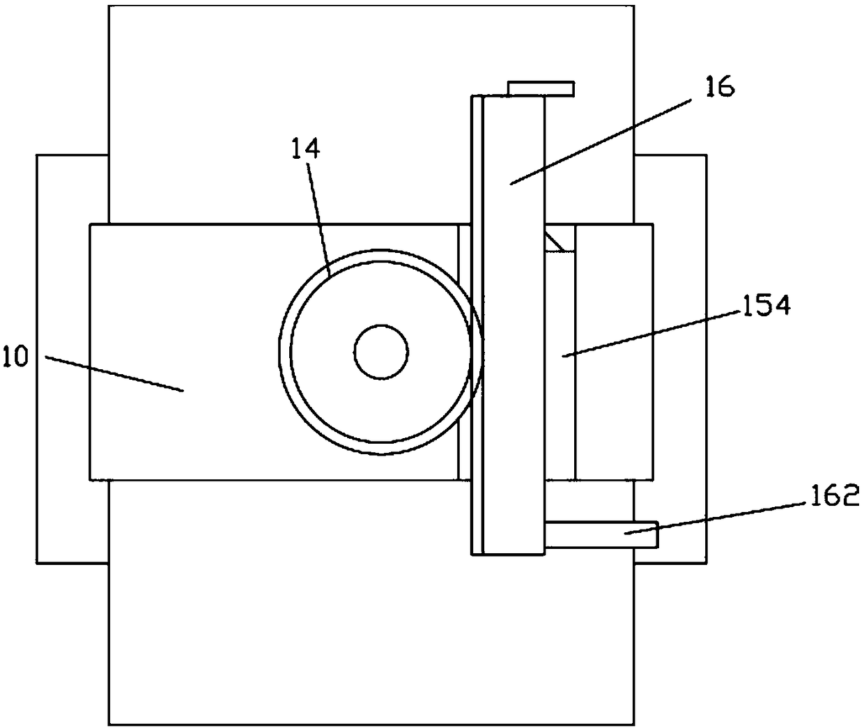
[0023] Examples, see e.g. Figure 1 to Figure 3 As shown in the figure, a rectangular rack pull valve mechanism for large-particle solid flow includes a rectangular valve body 10 and a bottom frame 20, and rectangular extension connecting sleeves 11 are formed on both ends of the rectangular valve body 10;

[0024] The bottom surface of the base plate of the rectangular valve body 10 is fixed with a main base plate 101, the left and right sides of the bottom surface of the main base plate 101 are fixed with vertical guide columns 102, and the left and right sides of the top plate of the chassis 20 are fixed with vertical support plates 21, two The top inner wall of the vertical support plate 21 is fixed with a transverse plate 22, and two vertical screw rods 23 are located on the left and right sides of the top plate of the underframe 20, and the bottom ends of the vertical screw rods 23 are hinged on the top plate of the underframe 20. The top of the straight screw 23 is hing...


PUM


Abstract

The invention discloses a movable type rectangular rack pulling type valve mechanism for large-particle solid circulation. The valve mechanism comprises a rectangular valve body and an underbed. Rectangular extension connection sleeve bodies are formed on two end faces of the rectangular valve body. A main base plate is fixed to the bottom face of a base plate of the rectangular valve body. Vertical guide columns are fixed to the left side and the right side of the bottom face of the main base plate. Vertical supporting plates are fixed to the left side and the right side of a top plate of theunderbed. Transverse plates are fixed to the inner side walls of the top ends of the two vertical supporting plates. Two vertical screws are located on the left side and the right side of the top plate of the underbed. The movable type rectangular rack pulling type valve mechanism for large-particle solid circulation can be mounted in large-particle solid substance transportation mechanisms for temporary use; the rectangular valve body is adopted; manufacturing is simple; large-particle solid substance transportation control is satisfied; mounting is convenient to conduct; the position can beadjusted higher or lower; plugging connection of the valve mechanism with an interface of transportation equipment can be guaranteed; in addition, valve plate rotation is achieved through pulling ofracks, and the transportation capacity is adjusted through the valve plate rotation; and adjustment is convenient to conduct, and control precision is high.

Description

Technical field: [0001] The invention relates to the technical field of valves, in particular to a movable large-grain solid flow pull-type valve mechanism with a rectangular rack. Background technique: [0002] Existing valves for liquid flow control generally use circular hole structures for delivery, and valves for some solid particle delivery generally use rectangular hole structures, which are simple to manufacture, low in cost, and low in sealing requirements. There is no such valve at present; [0003] Simultaneously, the use of existing valves all requires screw connection and fixing, etc., which are generally used for a long time, and are not suitable for a detachable connection structure for temporary use, which cannot meet the use of some flexible conveying mechanisms. [0004] Moreover, the existing valves generally adopt screw-type rotation or handle rotation to realize adjustment. The handle adjustment has unsatisfactory effect and low control accuracy, and th...

Claims


Application Information

Patent Timeline
IPC IPC(8): F16K3/02F16K3/314F16K3/316F16K3/36F16K27/04F16K31/50F16K31/54
CPCF16K3/0281F16K3/314F16K3/316F16K3/36F16K27/044F16K31/50F16K31/54
Inventor 徐亚维
Owner DONGGUAN LIANZHOU INTPROP OPERATION MANAGEMENT CO LTD
Why Eureka
Try Eureka