


Quick Research
Generate reliable direction feasibility study reports for your R&D in just a few steps.

Technical Q&A
Discover and master advanced knowledge NOW. Basics, ideas, possibilities, all at once.

Find Solutions
As an expert in R&D theories, this can generate solutions to your technical problems instantly.

Evaluate Feasibility
Analyze your overall solution with one click, know your potential R&D risks in advance.

Monitor Landscape
Get weekly tech updates, stay abreast of the latest tech innovations and key insights.
Electrospinning tubular stent collection device and electrospinning equipment
A collection device and electrospinning technology, applied in textiles and papermaking, filament/thread forming, fiber processing, etc., can solve the problems of difficult removal of tubular stents, avoid the original shape, increase desirability, and stable properties Effect
- Summary
- Abstract
- Description
- Claims
- Application Information
AI Technical Summary
Problems solved by technology
Method used
Image

Examples
Embodiment 1
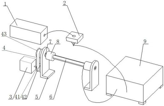
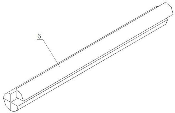
[0026] Such as Figure 1 to Figure 2 Shown is the first embodiment of the electrospinning tubular stent collection device of the present invention, comprising a support frame 5 and a collector rotatably connected to the support frame 5, the collector includes a split tubular structure 6 and a split-type structure for restraining The coupling 8 of the tubular structure 6, the coupling 8 is detachably connected to both ends of the split tubular structure 6; one end of the split tubular structure 6 is connected to a transmission mechanism, and the transmission mechanism is connected to Drive motor 3; the split tubular structure 6 is a conductive structure, a negative voltage is applied to the split tubular structure 6, and the fibers formed by the splitting of the charged jet released from the positive voltage end are directional suspended in the split tubular structure due to the action of the electric field force. Above structure 6.
[0027] During the implementation of this e...
Embodiment 2
[0033] Such as figure 1 Shown is an embodiment of the electrospinning device of the present invention, including the above-mentioned tubular support collection device, a DC power supply 9, a spinning needle 2 connected to the positive voltage terminal of the DC power supply 9, and a syringe pump communicated with the spinning needle 2 1. The tubular stent collection device is connected to the negative voltage terminal of the high-voltage power supply; the spinning needle 2 is arranged above the split tubular structure 6, and is used to inject a charged solution toward the tubular stent collection device.
[0034] In this embodiment, before electrospinning, the split tubular structure 6 is combined into a cylinder and fixed with a coupling 8, and the other end of the coupling 8 is installed on the transmission shaft 7 on both sides of the support frame 5, and then Turn on the power supply, the syringe pump 1 and the DC motor perform electrospinning, and the DC motor drives the ...
PUM
| Property | Measurement | Unit |
|---|---|---|
| angle | aaaaa | aaaaa |
Abstract
Description
Claims
Application Information
 - R&D Engineer
- R&D Manager
- IP Professional
- Industry Leading Data Capabilities
- Powerful AI technology
- Patent DNA Extraction
Browse by: Latest US Patents, China's latest patents, Technical Efficacy Thesaurus, Application Domain, Technology Topic, Popular Technical Reports.
© 2024 PatSnap. All rights reserved.Legal|Privacy policy|Modern Slavery Act Transparency Statement|Sitemap|About US| Contact US: help@patsnap.com