Cutting device for cutting tire component

A cutting device and component technology, applied in metal processing and other directions, can solve the problems of small contact area between the upper tool and tire components, easy to increase tool wear, and broken tool.

Active Publication Date: 2018-11-23
邦盟泓稻计量检测有限公司
View PDF3 Cites 0 Cited by
  • Summary
  • Abstract
  • Description
  • Claims
  • Application Information

AI Technical Summary

Problems solved by technology

[0002] Cutting devices for cutting tire components are known in two types; part-off cutters or disc and rod cutters, part-off cutters comprising an upper knife and a lower knife, each having a straight cutting edge, the upper knife along the The lower cutter moves vertically to form a cut in the tire component. The disc and rod cutters include a disc-shaped upper cutter and a rod-shaped lower cutter. The disc-shaped upper cutter travels in the longitudinal direction along the rod-shaped lower cutter while turning Several turns to cut the tire part, the rod-shaped lower knife has a larger cutting angle, the contact area between the upper knife and the tire part is significantly smaller, and the increased cutting angle reduces the pressure required for cutting the tire part In the prior art, due to the great toughness of the tire, the cutter is subjected to excessive stress during cutting, which easily increases the wear of the cutter and even breaks the cutter

Method used


Image

  • Cutting device for cutting tire component
  • Cutting device for cutting tire component
  • Cutting device for cutting tire component

Examples


Embodiment

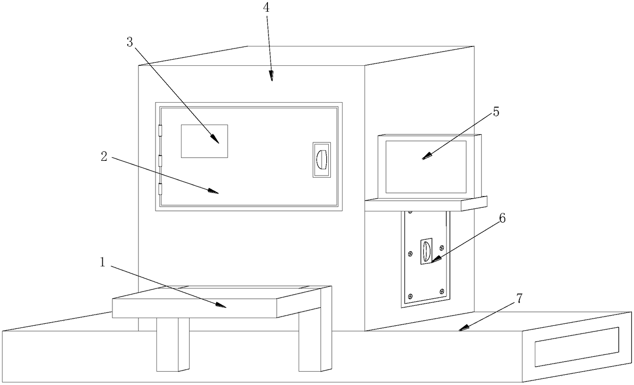
[0023] see Figure 1-Figure 4, the present invention provides a cutting device for cutting tire components, the structure of which includes a tripod 1, a protective door 2, a physical embrittlement cutting device 3, a cutting box 4, a control console 5, a maintenance door 6, and a supporting bottom plate 7. One end of the tripod 1 close to the physical embrittlement cutting device 3 is fixedly connected to the lower position of the front end face of the cutting box body 4 by electric welding, and the protective door 2 is mechanically connected to the middle position of the front end face of the cutting box body 4 through a hinge. , the cutting box 4 is provided with a physical embrittlement cutting device 3, and one end of the control console 5 close to the protective door 2 is fixedly connected to the middle position on the right side of the front end face of the cutting box 4 by electric welding. The maintenance door 6 is installed at the lower end position on the right side...


PUM


Abstract

The invention discloses a cutting device for cutting a tire component. The cutting device structurally comprises a foot frame, a protection door, a physical embrittlement cutting device, a cutting boxbody, a control operation table, a maintenance door and a supporting bottom plate. The end, close to the physical embrittlement cutting device, of the foot frame is fixedly connected to the lower position of the front end face of the cutting box body in an electric welding mode, the protection door is mechanically connected with the middle position of the front end face of the cutting box body through a hinge, the physical embrittlement cutting device is arranged inside the cutting box body, and the end, close to the protection door, of the control operation table is fixedly connected to themiddle position of the right side of the front end face of the cutting box body in an electric welding mode. A cold air guide mechanism is used for controlling a cold air exhaust mechanism to exhaustcold air into the cutting box body, a hardening effect is produced to a tire, therefore, the toughness of the tire is reduced, stress to a cutter is reduced during cutting, therefore, cutter abrasionis reduced, and the service life of the cutter is prolonged.

Description

technical field [0001] The present invention relates to the field of tire cutting, in particular to a cutting device for cutting tire components. Background technique [0002] Cutting devices for cutting tire components are known to be of two types; cut-off cutters, or disc and rod cutters, cut-off cutters comprising upper and lower cutters, each with a straight cutting edge, the upper cutter along the A lower cutter moves vertically to form a cut in a tire component. Disc and stick cutters include a disc upper cutter and a bar lower cutter. The disc upper cutter travels in the longitudinal direction along the bar lower cutter while turning over Several turns are used to cut the tire part, the rod-shaped lower cutter has a larger cutting angle, the contact area between the upper cutter and the tire part is significantly smaller, and the increased cutting angle reduces the pressure required to cut the tire part Due to the great toughness of the tire in the prior art, the cut...

Claims


Application Information

Patent Timeline
Patent Type & Authority Applications(China)
IPC IPC(8): B26D1/18B26D7/08B26D5/00B26D7/01B26D3/00
CPCB26D1/18B26D3/005B26D5/00B26D7/01B26D7/08
Inventor 王建勤
Owner 邦盟泓稻计量检测有限公司
Why Eureka
Try Eureka