Method for measuring laser-wire space

A technology for measuring light wire spacing and measuring light, which is applied in the direction of mechanical gap measurement, laser welding equipment, manufacturing tools, etc. It can solve the problems of unprofessional measurement methods of measuring tools, inconsistent welding seam formation, and incorrect measurement, etc., so as to achieve easy application and Storage, low cost, and easy operation

Inactive Publication Date: 2018-11-23
SHENYANG FORTUNE PRECISION EQUIP CO LTD
View PDF4 Cites 5 Cited by
  • Summary
  • Abstract
  • Description
  • Claims
  • Application Information

AI Technical Summary

Problems solved by technology

[0002] In laser wire-filling welding aluminum alloy technology, the distance between the light wires has a great influence on the shape of aluminum alloy laser wire-filling welding. However, measurement errors are often caused by unprofessional measuring tools and incorrect measurement methods, resulting in inconsistent weld formation.

Method used


Image

  • Method for measuring laser-wire space
  • Method for measuring laser-wire space

Examples


Embodiment

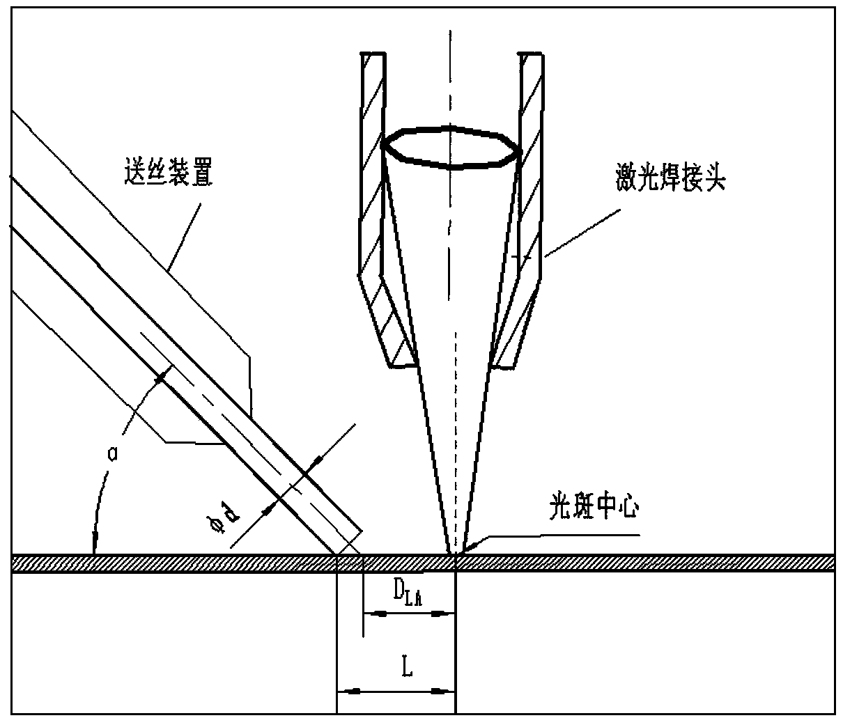
[0023] 1) After adjusting the amount of defocus, the extension length of the wire stem, and the angle of laser wire filling, after the above-mentioned best data are obtained through experiments, they are constant parameters.

[0024] 2) The center of the laser spot is aligned with the scale line, so that the center of the laser spot falls on the scale line, and the light spots are evenly distributed on both sides of the scale line.

[0025] 3) Trim the wire to a small distance from the upper surface of the measuring ruler, and then use the wire height adjustment device to make fine adjustments until the far end of the wire is close to the upper surface of the measuring ruler.

[0026] 4) Read through the CCD magnifying display device, and the reading accuracy is 0.2mm.

[0027] 5) Make fine adjustments through the wire filling adjustment device to ensure that the distance between the light wires is within the required range. Knowing the DAL, the L value can also be calculated...


PUM

PropertyMeasurementUnit
Widthaaaaaaaaaa

Abstract

The invention discloses a method for measuring a laser-wire space in a special welding technology of laser wire filling. According to the method disclosed by the invention, the best laser-wire space DAL required by formation of weld joints can be accurately measured through an experiment; the laser-wire space DAL indicates a distance from a laser spot center to a contact point of the diameter center of a welding wire to the surface of a workpiece; when the laser-wire space is 0mm, although the front faces of the weld joints are molded preferably, the melting widths of the back sides are obviously different from each other in different areas, acquisition of the weld joints with good uniform performance is not facilitated. When the welding velocity is 4.2m / min, the laser-wire space is strictly controlled to be in a range of plus 0.8 to plus 1.4; when the welding velocity is 3.0m / min, the laser-wire space needs to be controlled in a range of plus 0.4 to plus 2m; if the laser-wire space isover-large, because a distance between the welding wire and a heat source is longer, the laser wire cannot be completely molten under the effect of plasma cloud, so that the defects of undercuts, welded leakage, wire stationing and the like locally produced on the weld joints are caused.

Description

technical field [0001] The present invention relates to a special laser wire-filling welding technology for the IC equipment manufacturing industry. In the laser wire-filling welding technology center, the distance between the light wires has a great influence on the shape of the weld seam, which is an important welding variable. The present invention describes a method for measuring the distance between optical filaments. Background technique [0002] In laser wire-filling welding aluminum alloy technology, the distance between the light wires has a great influence on the shape of aluminum alloy laser wire-filling welding, but measurement errors are often caused by unprofessional measurement tools and incorrect measurement methods, resulting in inconsistent weld formation. Accurate measurement of filament spacing D AL It is convenient to control variables in production and ensure the quality consistency of welding products. By means of the present invention, the optimal l...

Claims


Application Information

Patent Timeline
IPC IPC(8): B23K26/21B23K26/70G01B5/14
CPCB23K26/21B23K26/70G01B5/14
Inventor 李文明李生智谯永鹏张维
Owner SHENYANG FORTUNE PRECISION EQUIP CO LTD
Why Eureka
Try Eureka