
Separated machining method of upper die and material pressing plate of stamping die

A stamping die and processing method technology, applied in the field of stamping die upper die and binder plate parts processing, can solve the problems of prolonging the standby time of CNC machine tools, reduce workload and labor intensity, reduce processing operation content, and reduce rework Effect

Active Publication Date: 2018-11-23
柳州福臻车体实业有限公司
View PDF5 Cites 2 Cited by
  • Summary
  • Abstract
  • Description
  • Claims
  • Application Information

AI Technical Summary

Problems solved by technology

[0006] It can be seen from the traditional processing process of stamping dies that there are multiple repeated disassembly and assembly work; steps 5, 6, 9, and 10 need to be operated on the CNC machine tool, which prolongs the standby time of the CNC machine tool

Method used


Image

  • Separated machining method of upper die and material pressing plate of stamping die
  • Separated machining method of upper die and material pressing plate of stamping die
  • Separated machining method of upper die and material pressing plate of stamping die

Examples


Embodiment 1

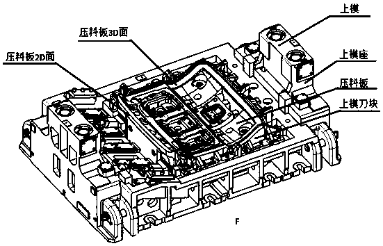
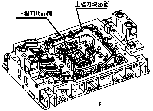
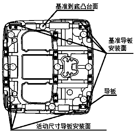
[0034] processed as Figure 1-4 For the upper mold and pressing plate shown, the following operation steps are adopted:

[0035] The method for processing the stamping die upper die and the binder plate separately comprises the following steps:

[0036] A. Obtain the X and Y coordinates based on the F direction in front of the upper die and the reference base block mounting surface; define the X positive and Y positive directions, and define the guide sliding surface in the X positive and Y negative directions of the upper die base as the reference guide sliding surface. The sliding guide surface of the upper die base in the X negative and Y positive directions is defined as the movable size guide sliding surface, and the bottom pad mounting surface of the upper die is defined as the reference bottom pad mounting surface;

[0037] B. For the binder plate, based on the front F direction of the mold, the guide plate installation surface of the binder plate corresponding to the ...


PUM


Abstract

The invention aims to provide a separated machining method of an upper die and a material pressing plate of a stamping die. The separated machining method comprises the following steps: establishing acoordinate system I of X, Y and Z for the upper die; establishing a coordinate system II of X, Y and Z for the material pressing plate; machining the upper die and the material pressing plate respectively based on the coordinate system I and the coordinate system II; then, assembling the upper die and the material pressing plate together; and performing side pin hole machining. According to the separated machining method of the upper die and the material pressing plate of the stamping die, the machining and bedding-in benchmark uniformity of the upper die and the material pressing plate can be ensured; the matching precision of the upper die and the material pressing plate can be ensured; the mode of combining the upper die and the material pressing plate of the stamping die in sequence is converted into the mode of machining the upper die and the material pressing plate of the stamping die separately; a machining manufacturing process is simplified and standardized; and repeated disassembling and assembling work is reduced and numerical control standby time is shortened.

Description

technical field [0001] The invention belongs to the field of mold processing, and in particular relates to a separate processing method for an upper mold and a binder plate of a stamping mold. Background technique [0002] Panel parts such as automobile body panels and automobile chassis are stamped and formed by stamping dies. In the traditional processing and manufacturing process of stamping dies, in order to ensure the matching accuracy of the upper die and the binder plate, it is necessary to assemble the upper die and the binder plate into one body for combined processing. [0003] The stamping die is composed of upper die base, pressing plate, upper die block and other parts. The time required for the blank production of these parts is different, the aging treatment time is different, the production time required by different outsourcing manufacturers is different and factors such as logistics lead to the The time for blanks to return to the factory is not uniform, a...

Claims


Application Information

Patent Timeline
Patent Type & Authority Applications(China)
IPC IPC(8): B21D37/20
CPCB21D37/205
Inventor 冯旺旺马文斌雷庆营冯海波刘禹锡叶玉杰
Owner 柳州福臻车体实业有限公司
Learn More