Stator permanent-magnet thin-type bearingless switch reluctance machine

A switched reluctance motor, sheet type technology, applied in the direction of magnetic circuit shape/style/structure, magnetic circuit, electromechanical device, etc., can solve the problem of high speed and high power density, high critical speed and axial Long length and other problems, to achieve the effect of short axial length, simple control, and less driving circuits

Active Publication Date: 2018-11-20
宁波银禧机械科技有限公司
View PDF5 Cites 8 Cited by
  • Summary
  • Abstract
  • Description
  • Claims
  • Application Information

AI Technical Summary

Problems solved by technology

In addition, to realize the stable suspension of the rotor with five degrees of freedom, any combination of axial single-degree-of-freedom magnetic bearings, radial two-degree-of-freedom magnetic bearings, three-degree-of-freedom radial-axial magnetic bearings, and two-degree-of-freedom bearingless switched reluctance motors must be used. The five-degree-of-freedom bearingless switched reluctance motor drive system is bulky, has a long axial length, and has a high critical speed, which makes it difficult to reflect the advantages of high speed and high power density of bearingless motor technology

Method used


Image

  • Stator permanent-magnet thin-type bearingless switch reluctance machine
  • Stator permanent-magnet thin-type bearingless switch reluctance machine
  • Stator permanent-magnet thin-type bearingless switch reluctance machine

Examples


Embodiment Construction

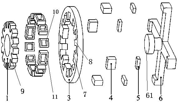
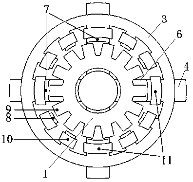
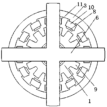
[0025] Such as Figure 1~6 A stator permanent-magnet laminar type bearingless switched reluctance motor shown includes a stator and a rotor 1, the side of the rotor 1 is provided with 12 rotor teeth 9, and the stator is composed of a stator core 3, a torque winding 10. The suspension winding 11, the first magnetic bridge 4, the permanent magnet 5, and the second magnetic bridge 6 are stacked in the axial direction. The stator core 3 is made into a ring, and the inner ring is arranged in the x direction and the y direction There are a total of four suspension teeth 7, two torque teeth 8 are evenly arranged on the inner ring of the stator core 3 between two adjacent suspension teeth 7, and the suspension winding 11 and the torque winding 10 are respectively wound on the suspension teeth 7 and on the torque tooth 8; the width of the suspension tooth 7 is greater than the width of the torque tooth 8, and the width of the suspension tooth 7 is greater than one pole pitch of the mot...


PUM


Abstract

The invention discloses a stator permanent-magnet thin-type bearingless switch reluctance machine. The stator permanent-magnet thin-type bearingless switch reluctance machine comprises a stator and arotor, wherein rotor teeth are arranged at an edge part of the rotor, the stator comprises a stator core, first magnetic conduction bridges, permanent magnets and a second magnetic conduction bridge,the stator core is in an annular shape, a plurality of suspension teeth are uniformly arranged at an inner ring of the stator core, a plurality of torque teeth are uniformly arranged at the inner ringof the stator core between two adjacent suspension teeth, a suspension winding and a torque winding are respectively wound around the suspension teeth and the torque teeth, the rotor is coaxially arranged in an inner cavity of the stator core, the stator teeth, the suspension teeth and the torque teeth are arranged at intervals to form a radial working gap, a central hole is coaxially formed in the rotor, the second magnetic conduction bridge comprises a central post and a plurality of magnetic conduction arms, the plurality of magnetic conduction arms are uniformly arranged on the same circumference of the central post, each magnetic conduction arm is connected with the first magnetic conduction bridge by the permanent magnet, the first magnetic conduction bridges are attached onto the stator core, the central post is inserted into the central hole, and the central post and the central hole are arranged at intervals to form a central working air gap.

Description

technical field [0001] The invention relates to the technical field of motor manufacturing, in particular to a stator permanent magnet thin-plate bearingless switched reluctance motor. Background technique [0002] Bearingless motors have no friction, no wear, no lubrication and no seals, and are easy to achieve higher speed and higher power operation. They have broad application prospects in aerospace, turbomolecular pumps, flywheel energy storage, sealed pumps, high-speed electric spindles, etc. . Bearingless motors are mainly divided into three types: bearingless asynchronous (induction) motors, bearingless permanent magnet synchronous motors and bearingless switched reluctance motors. In particular, the bearingless switched reluctance motor has the advantages of simple structure, high mechanical strength, flexible control, fault tolerance and robustness, and has broad application prospects in the fields of electric vehicles, aerospace, and household appliances. [0003...

Claims


Application Information

Patent Timeline
Patent Type & Authority Applications(China)
IPC IPC(8): H02K1/12H02K1/22H02N15/00
CPCH02K1/12H02K1/22H02K2201/03H02N15/00
Inventor 张涛陈万鲁庆丁祖军丁卫红唐中一王业琴
Owner 宁波银禧机械科技有限公司
Why Eureka
Try Eureka