
Method for identifying damage and quantitatively analyzing damage degree of main girder of bridge erecting machine

A damage degree, quantitative analysis technology, applied in design optimization/simulation, special data processing applications, instruments, etc., can solve problems such as structural damage to the main girder of the bridge erection machine, safety accidents, and failure to detect in time, and achieve economical and reliable results.

Active Publication Date: 2018-11-20
SHIJIAZHUANG TIEDAO UNIV
View PDF4 Cites 19 Cited by
  • Summary
  • Abstract
  • Description
  • Claims
  • Application Information

AI Technical Summary

Problems solved by technology

[0006] The purpose of the present invention is to provide a bridge erecting machine main girder damage identification and damage degree quantitative analysis method to overcome the shortcomings of the prior art damage identification technology that requires the bridge erecting machine main girder before damage mode and physical parameters, so as to adapt to the bridge erecting machine. During the hole operation, the supporting state of the main girder of the bridge erecting machine changes randomly at any time, and solves the problem that the structural damage of the main beam of the bridge erecting machine cannot be detected in time and easily causes major safety accidents

Method used


Image

  • Method for identifying damage and quantitatively analyzing damage degree of main girder of bridge erecting machine
  • Method for identifying damage and quantitatively analyzing damage degree of main girder of bridge erecting machine
  • Method for identifying damage and quantitatively analyzing damage degree of main girder of bridge erecting machine

Examples


Embodiment Construction

[0027] The present invention will be described in detail below in conjunction with the embodiments and the accompanying drawings. The protection scope of the present invention is not limited to the embodiments, and any changes made by those skilled in the art within the scope defined in the claims also belong to the protection scope of the present invention.

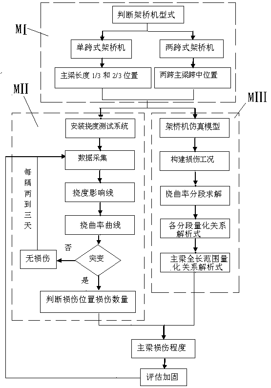
[0028] The method for identifying damage to the main girder of the bridge erecting machine and quantifying the damage degree of the present invention is to perform quantitative analysis on whether the main girder of the bridge erecting machine is damaged, the location of the damage, and the degree of damage on the basis of the deflection monitoring data obtained during the operation of the bridge erecting machine. Such as figure 1 As shown, based on the status quo of the main girder support changing at any time during the operation of the bridge erecting machine, the main girder structure type judgment module (MI), dama...


PUM


Abstract

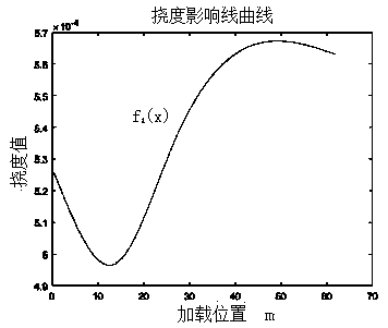
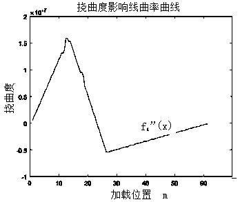
The invention relates to a method for identifying damage and quantitatively analyzing damage degree of a main girder of a bridge erecting machine. Based on the present situation that the main girder support changes with time in the operation process of the bridge erecting machine, a main girder structure type judging module MI, a damage identifying and analyzing module MII and a damage quantitatively analyzing module MIII are established. The damage identifying and analyzing module includes: (1) a deflection test system is installed; (2) deflection detection data is collected; (3) the detection data is processed to obtain a deflection influence line f1 (x); (4) the deflection influence line is processed to obtain a deflection rate curve f1 "(x); (5) whether mutation exists is judged; (6) the locations and quantity of injuries are judged. The damage quantitatively analyzing module includes: (1) a numerical simulation model is established; (2) n kinds of damage conditions are constructed, and m damage degrees are constructed for each kind of damage condition. (3) the deflection values of different damage degrees are obtained, and the relationship curve of deflection rate and damage degree is defined. (4) the relationship of deflection rate and damage degree of the main girder of the bridge erecting machine is obtained. The invention solves the problem that the structural damage of the main girder of the bridge erecting machine cannot be found in time, and the bridge erecting machine is easy to cause a serious safety accident.

Description

technical field [0001] The invention belongs to the technical field of mechanical structure damage identification and analysis, and relates to a damage identification and damage degree quantitative analysis method for a main girder of a bridge erecting machine. Background technique [0002] Bridge erecting machines are widely used in bridge erection construction in high-speed railway construction. The operating environment is harsh, and they are often transferred to other sites. Damages such as weld corrosion and plate cracking occur from time to time, which can easily lead to major safety accidents. In recent years, safety accidents of bridge erecting machines have occurred frequently, causing heavy casualties and property losses. In order to detect potential safety hazards of bridge erecting machines early, the problem of structural damage identification of bridge erecting machines has attracted increasing attention. [0003] Structural damage identification has always be...

Claims


Application Information

Patent Timeline
IPC IPC(8): G06F17/50
CPCG06F30/13G06F30/20
Inventor 陈士通程泳李义强许宏伟张耀辉孙志星
Owner SHIJIAZHUANG TIEDAO UNIV
Learn More