
Hose follow-up device and hydraulic grab machine

A technology of follow-up device and hose, which is applied in the direction of earth mover/shovel, construction, etc., can solve the problems of low service life of hose, failure to find and maintain in time, complex structure of synchronous lifting technology, etc., and achieve damage reduction , the effect of improving the service life

Active Publication Date: 2014-06-18
XCMG CONSTR MACHINERY
View PDF6 Cites 0 Cited by
  • Summary
  • Abstract
  • Description
  • Claims
  • Application Information

AI Technical Summary

Problems solved by technology

[0007] One of the objectives of the present invention is to propose a hose follower and a hydraulic grab machine equipped with the hose follower, which solves the technical problem of low service life of the hose in the prior art
[0008] The preferred technical solution among the many technical solutions provided by the present invention also solves the problem that the existing synchronous lifting technology has a complicated structure, and once a problem occurs, it cannot be found and maintained in time, which will be described in detail below

Method used


Image

  • Hose follow-up device and hydraulic grab machine
  • Hose follow-up device and hydraulic grab machine
  • Hose follow-up device and hydraulic grab machine

Examples


Embodiment Construction

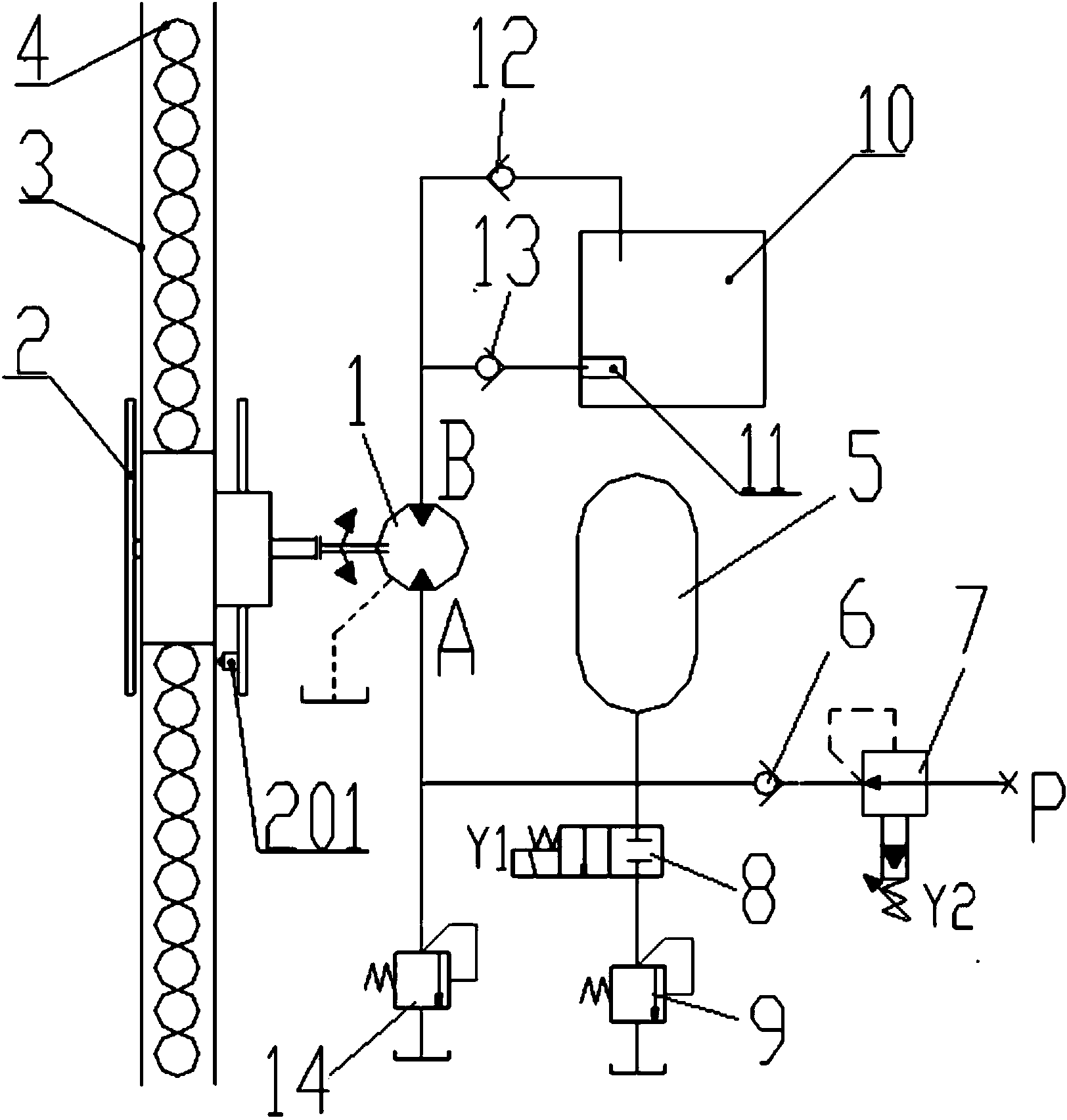
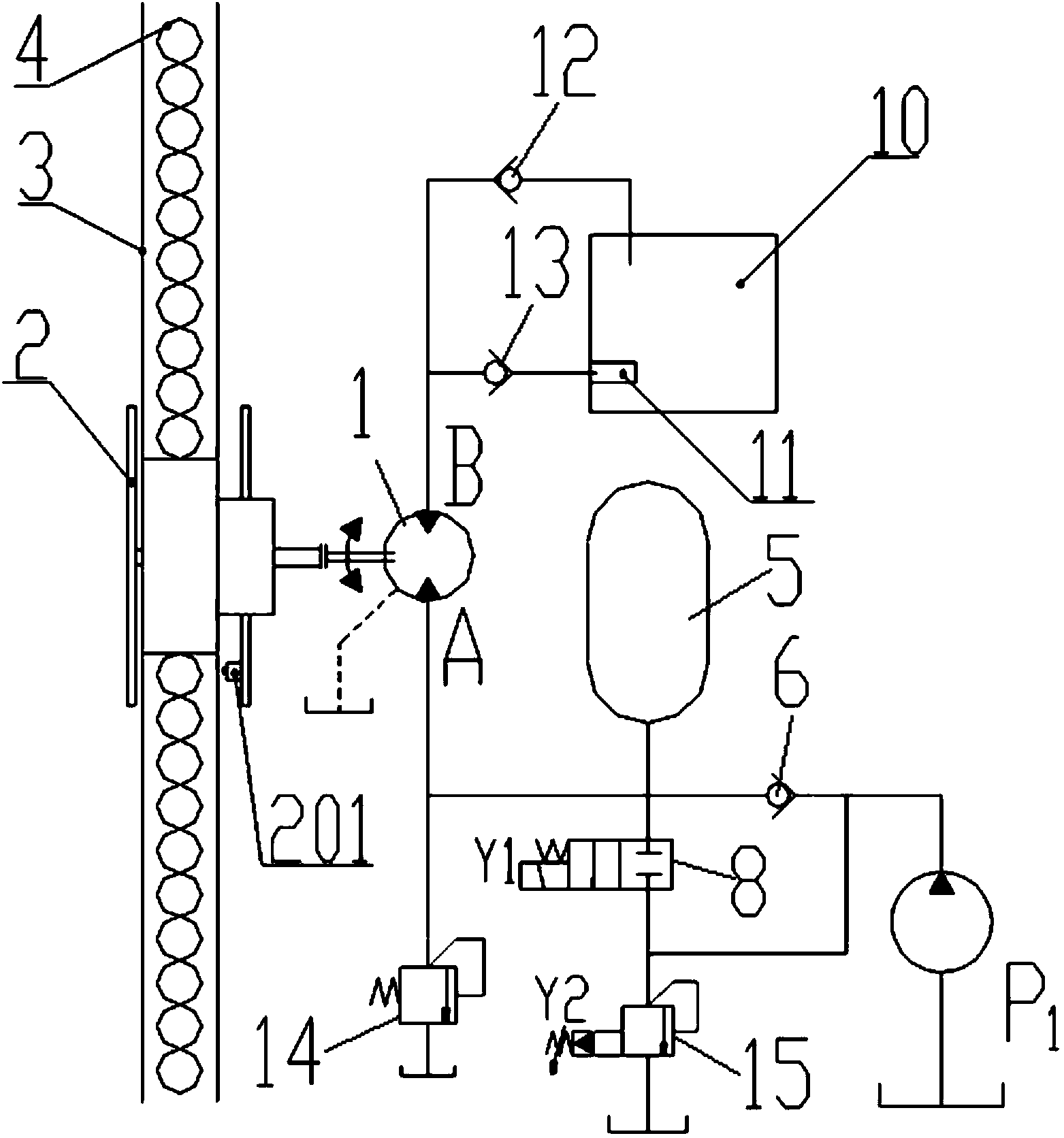
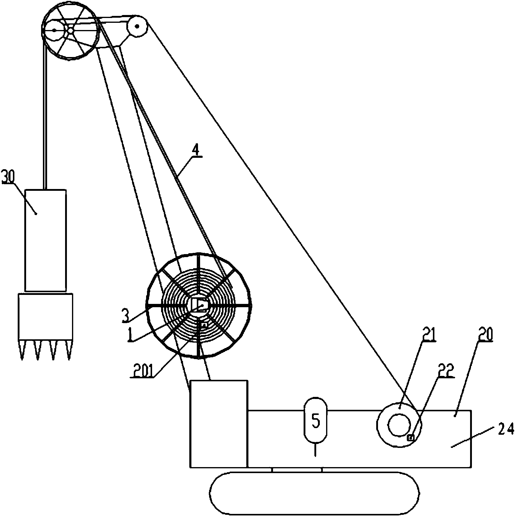
[0042] Below you can refer to the accompanying drawings Figure 1 ~ Figure 3 And the content of the text to understand the content of the present invention and the differences between the present invention and the prior art. The technical solution (including the preferred technical solution) of the present invention will be further described in detail below by way of the accompanying drawings and listing some optional embodiments of the present invention. It should be noted that: any technical feature and any technical solution in this embodiment are one or more of a variety of optional technical features or optional technical solutions. Citing all the alternative technical features and alternative technical solutions of the present invention, it is not convenient for the implementation of each technical feature to emphasize that it is one of the optional multiple implementation modes, so those skilled in the art should know that: Replace any technical means provided by the p...


PUM


Abstract

The invention discloses a hose follow-up device and a hydraulic grab machine, and relates to the technical field of engineering machines. The hose follow-up device and the hydraulic grab machine solve the technical problem that in the prior art, the service life of a hose is short. The hose follow-up device comprises an energy storage element, a hose and a hydraulic energy conversion drive mechanism, and the hydraulic energy conversion drive mechanism is connected between the energy storage element and the hose. Mechanical energy generated when the hose stretches outwards can be converted into hydraulic energy through the hydraulic energy conversion drive mechanism and then the hydraulic energy is stored in the energy storage element, the hydraulic energy conversion drive mechanism can also receive the hydraulic energy released by the energy storage element and drive the hose to be withdrawn through the hydraulic energy. The hydraulic grab machine comprises a hydraulic grab body, a grab body opening and closing oil cylinder, a rotary table and the hose follow-up device. The hose follow-up device and the hydraulic grab machine are used for prolonging the service life of the hose and reducing power losses of a hydraulic system.

Description

technical field [0001] The invention relates to the technical field of engineering machinery, in particular to a hose follower and a hydraulic grab machine provided with the hose follower. Background technique [0002] Diaphragm wall hydraulic grab is one of the hydraulic grab machines. It is a basic engineering construction machine with low construction cost and high construction efficiency. Its excavation depth can reach 100 meters. The closing and opening of the diaphragm wall hydraulic grab body is driven by the cylinder on its frame (the cylinder can be called: bucket body opening and closing cylinder). When the hydraulic grab is lifted or lowered, the hose wound on the reel should also be lifted and lowered synchronously with the grab body. How to achieve synchronization is a key technology of the hydraulic grab. [0003] In order to solve the above problems, in the prior art, a pump is used to directly drive a hydraulic motor to drive the hose up and down. At presen...

Claims


Application Information

Patent Timeline
IPC IPC(8): E02F9/22
Inventor 吴兴丛贺雷刘松
Owner XCMG CONSTR MACHINERY
Learn More