An embedded double-spool pilot control mechanism and a fluid control valve

A technology of fluid control valves and double spools, which is applied in the direction of fluid pressure actuators, mechanical equipment, servo motor components, etc., and can solve the problems of reduced reliability, increased cost, and greater impact of control valves

Active Publication Date: 2020-07-03
赵荣凯
View PDF7 Cites 0 Cited by
  • Summary
  • Abstract
  • Description
  • Claims
  • Application Information

AI Technical Summary

Problems solved by technology

[0005] In order to overcome the hydraulic force caused by the fluid flow on the valve core 013 when the valve core 013 is opened, the control valve with the above structure must increase the electromagnetic thrust. In the prior art, the electromagnetic thrust is realized by using a large-sized electromagnet and increasing the input current. In this way, the volume and weight of the whole valve will be greatly increased, and the cost will also increase accordingly, and this kind of control valve is greatly affected by the controlled flow and pressure, and the performance of the valve under different flow and pressure Large changes and instability, especially when applied to high-pressure, medium-to-large flow systems, the hydraulic force generated by the fluid flow on the valve core will be further increased. At this time, only by increasing the electromagnetic thrust will cause the control valve to The reliability decreases rapidly, and the service life is greatly reduced. Therefore, in the high-pressure, medium-to-large flow system, two-stage valves are currently used for control. The pilot-stage valve is superimposed on the power-stage valve, and the pilot-stage valve is used to control the power stage. The displacement of the power stage spool of the valve, and the power stage spool controls the main oil circuit

Method used


Image

  • An embedded double-spool pilot control mechanism and a fluid control valve
  • An embedded double-spool pilot control mechanism and a fluid control valve
  • An embedded double-spool pilot control mechanism and a fluid control valve

Examples


Embodiment Construction

[0057] The invention provides an embedded double-spool pilot control mechanism and a fluid control valve to achieve the purposes of simple structure, small volume, light weight, low cost and high reliability.

[0058] The following will clearly and completely describe the technical solutions in the embodiments of the present invention with reference to the accompanying drawings in the embodiments of the present invention. Obviously, the described embodiments are only some, not all, embodiments of the present invention. Based on the embodiments of the present invention, all other embodiments obtained by persons of ordinary skill in the art without making creative efforts belong to the protection scope of the present invention.

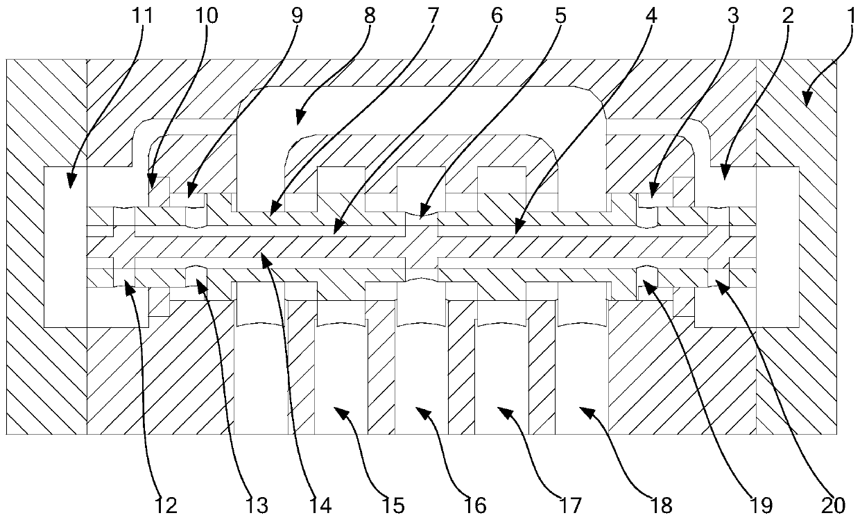
[0059] see image 3 , image 3 It is a schematic structural diagram of the embedded double-spool pilot-control mechanism provided by the first embodiment of the present invention.

[0060] The present invention provides an embedded double-spool pilot ...


PUM


Abstract

The invention discloses an embedded double valve core guide and control mechanism and a fluid control valve. The guide and control mechanism includes a valve body, a power level valve core and a pilotlevel valve core; the power level valve core is slidingly arranged in the valve body, a left oil return cavity, a left control cavity, a right control cavity and a right oil return cavity are formedbetween the power level valve core and the valve body, and an oil inlet hole is arranged in the power level valve core; the pilot level valve core is arranged in the power level valve core, and a leftinterval channel and a right interval channel are formed between the pilot level valve core and the power level valve core; when the pilot level valve core moves to the left relative to the power level valve core, a flow passage area between the left control cavity and the left oil return cavity and between the right control cavity and the oil inlet hole is increased, and the flow passage area between the left control cavity and the oil inlet hole and between the right control cavity and the right oil return cavity is reduced; when the pilot level valve core moves to the right relative to thepower level valve core, and a principle is same. The guide and control mechanism is simple in structure, small in volume, light in weight, low in cost, is small in a cross section of the pilot levelvalve core, is not easily influenced by liquid power, and is high in reliability.

Description

[0001] This application claims the priority of the Chinese patent application with the application number 201710355857.9 and the title of the invention "An Embedded Double-Spool Guidance and Control Mechanism and Fluid Control Valve" submitted to the China Patent Office on May 19, 2017. technical field [0002] The invention relates to the technical field of fluid control, in particular to an embedded double-spool pilot control mechanism and a fluid control valve. Background technique [0003] Fluid control valves, especially hydraulic valves, play the role of controlling flow, pressure and switching oil circuits, and are an indispensable part of hydraulic systems. According to different control accuracy, they can be divided into electromagnetic switch valves, proportional valves, and servo valves; The size of the flow capacity is divided into; single-stage valve (direct-acting valve), two-stage valve. [0004] In the prior art, see figure 1 , figure 1 It is a structural s...

Claims


Application Information

Patent Timeline
Patent Type & Authority Patents(China)
IPC IPC(8): F15B13/02
CPCF15B13/023
Inventor 赵荣凯
Owner 赵荣凯
Why Eureka
Try Eureka