Eureka AIR delivers breakthrough ideas for toughest innovation challenges, trusted by R&D personnel around the world.

Data transmission cooperation control system and method, storage medium and interaction equipment

A collaborative control and data transmission technology, applied in the field of data transmission, can solve problems such as response confusion and source screen conflicts, and achieve the effects of reducing capacity requirements, resolving conflicts and responding to confusion

Active Publication Date: 2018-11-16
GUANGZHOU SHIYUAN ELECTRONICS CO LTD +1
View PDF17 Cites 3 Cited by
  • Summary
  • Abstract
  • Description
  • Claims
  • Application Information

AI Technical Summary

Problems solved by technology

[0003] In this screen transfer method, at the same time, the receiving end may click on the same place on the source screen and touch back. If there is no good multi-person collaboration control method, the source screen will conflict and cause a response confusion

Method used


Image

  • Data transmission cooperation control system and method, storage medium and interaction equipment
  • Data transmission cooperation control system and method, storage medium and interaction equipment
  • Data transmission cooperation control system and method, storage medium and interaction equipment

Examples


Embodiment 1

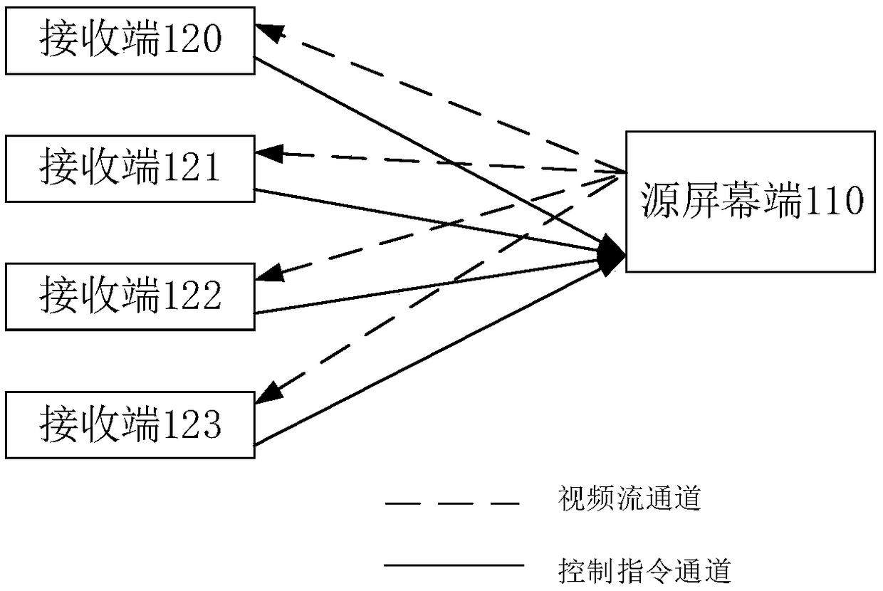
[0033] figure 1 A schematic diagram of the composition of a data transmission cooperative control system provided in this embodiment, as shown in figure 1 As shown, including video sending end and 4 receiving ends (120-123);

[0034] It should be noted that the number of receivers is not limited to the number given in this embodiment, and the number of receivers is limited not to exceed the computing capability and network routing capability of the source screen.

[0035] In the system, the video sending end includes a source screen end 110, and a video stream channel and a control command channel are established between the source screen end and each receiving end; each video stream channel or control command channel can use a socket channel.

[0036] Specifically, the source screen and all receivers are set under the same local area network; the source screen can use a fixed IP address and port number, and the receiver establishes a socket based on TCP or UDP with the IP ad...

Embodiment 2

[0075] Figure 4 A schematic composition diagram of a data transmission cooperative control system provided for this embodiment, as shown in 4, includes a source screen terminal 410, a media stream forwarding server 430, a control instruction server 440, and multiple receiving terminals (420-42N), Wherein, the source screen terminal 410, the media stream forwarding server 430 and the control instruction server 440 form the video sending end, and the number of receivers is limited by the computing capability and network routing capability of the media stream forwarding server and the control instruction server.

[0076] The media stream forwarding server 430 establishes video stream channels between the source screen end 410 and a plurality of receivers, and through the video stream channels, the source screen end 410 sends screen video streams to each receiver; realizes the synchronous display of the source screen end and the desktop of the receiver end;

[0077] The control c...

Embodiment 3

[0093] Figure 7 A flow chart of a data transmission cooperative control method provided in this embodiment, as shown in 7, specifically includes:

[0094] Step S710, establishing a video stream channel;

[0095]sending video stream data to at least one receiving end through a video stream channel;

[0096] Specifically, the same method as that in Embodiment 1 may be used to establish a video stream channel.

[0097] Step S720, establishing a control command channel;

[0098] Specifically, the same method as that in Embodiment 1 may be used to establish a control instruction channel.

[0099] Step S730, respectively receiving the control commands sent by at least one receiving end through the control command channel;

[0100] The control command sent by the receiving end can be packaged by the receiving end according to the obtained desktop touch event according to a certain format; it can also be packaged according to a certain format by the mouse event generated by the m...


PUM


Abstract

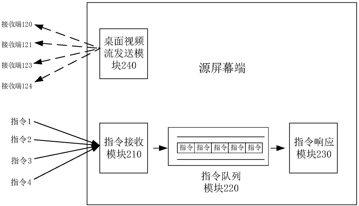
The invention relates to a data transmission cooperation control system and method, a storage medium and interaction equipment, and belongs to the technical field of data transmission. The system comprises a video transmitting terminal and at least one receiving terminal, the video transmitting terminal is a source screen terminal, a video flow passage and a control instruction passage are established, and control instructions transmitted by the at least one receiving terminal are received through the control instruction passage respectively; one of the receiving terminals is selected according to locked preset conditions, and responding is sequentially conducted on the control instructions transmitted by the receiving terminals until a control instruction which meets unlocking preset conditions and is transmitted by the receiving terminals is received; when there exists too many receiving terminals, the video transmitting terminal further comprises a media flow transferring server anda control instruction server, the video flow passage is established by adopting the media flow transferring server, and the control instruction server is adopted to establish the control instructionpassage. By means of the system and the method, conflicts and responding chaos caused by the simultaneous controlling of desktop synchronization are effectively solved, and the demands of the computing capability and the capability of network routes on the source screen terminal are greatly reduced.

Description

technical field [0001] The present invention relates to the technical field of data transmission, in particular to a data transmission cooperative control system, method, storage medium and interactive equipment. Background technique [0002] With the continuous development of screen transmission technology, the screen of one device (source screen end) is shared with multiple other device screens (receiver end), and the interactive operation interaction between the receiver end and the source screen end is realized through touch back transmission , become a trend. [0003] In this screen transfer method, at the same time, the receiving end may click on the same place on the source screen and touch back. If there is no good multi-person collaboration control method, the source screen will conflict and cause a response confusion. Contents of the invention [0004] In view of the above analysis, the present invention aims to provide a data transmission cooperative control s...

Claims


Application Information

Patent Timeline
Patent Type & Authority Applications(China)
IPC IPC(8): G06F9/451G06F3/14G06F3/0488G06F3/0487
CPCG06F3/0487G06F3/0488G06F3/1454G06F9/452
Inventor 郭庆伟
Owner GUANGZHOU SHIYUAN ELECTRONICS CO LTD
Why Eureka
Eureka Blog
Learn More