Method for discriminating depth of nonconductor defect based on multi-pair electrode capacitance imaging detection technology

A technology of capacitive imaging and multiple pairs of electrodes, which is used in measurement devices, material analysis by electromagnetic means, instruments, etc., can solve problems such as multi-time, only the upper or lower information of non-conductive materials, and low efficiency.

Active Publication Date: 2018-11-16
CHINA UNIV OF PETROLEUM (EAST CHINA)
View PDF5 Cites 3 Cited by
  • Summary
  • Abstract
  • Description
  • Claims
  • Application Information

AI Technical Summary

Problems solved by technology

[0003] Although single-pair electrode capacitive imaging detection technology can detect conductor surface defects and non-conductor internal defects, the detection results can only roughly reflect the length and width information of defects, and cannot reflect the depth information of non-conductor internal defects
With the rapid development of non-destructive testing technology toward refinement and visualization, single-pair electrode capacitance imaging detection, which lacks the important parameter of defect depth information, faces many disadvantages; To a certain extent, it can reflect the depth information of non-conductor internal defects. During the detection process, the conductor material needs to be placed under the non-conductor material, and the reflected defect depth information is only the upper or lower part of the non-conductor material; and for the same It takes a lot of time to scan the defect multiple times, and the efficiency is low; at the same time, when the single-pair electrode capacitive imaging detection technology detects defects under multiple lift-off heights, it is necessary to accurately grasp the variation range of the lift-off height. If the lift-off height If the grasp is not accurate, it will cause misjudgment of the depth information of the internal defects of non-conductor materials, resulting in inaccurate test results

Method used


Image

  • Method for discriminating depth of nonconductor defect based on multi-pair electrode capacitance imaging detection technology
  • Method for discriminating depth of nonconductor defect based on multi-pair electrode capacitance imaging detection technology
  • Method for discriminating depth of nonconductor defect based on multi-pair electrode capacitance imaging detection technology

Examples


Embodiment 1

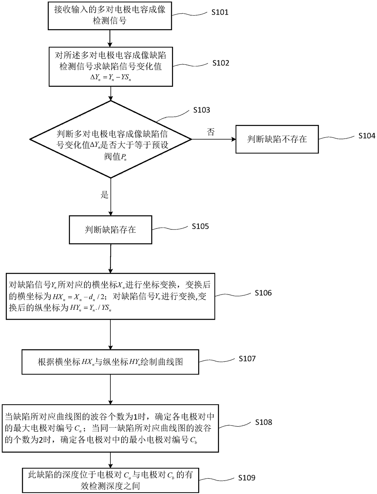
[0018] figure 1 Schematic diagram of a method for judging the depth of non-conductor defects based on multi-pair electrode capacitive imaging detection technology provided for the embodiment of the present invention Figure 1 , as shown, including:

[0019] S101. Receive input capacitance imaging detection signals of multiple pairs of electrodes, wherein the detection signals of capacitance imaging of multiple pairs of electrodes include each electrode pair (C 1 、C 2 ...C n ) to the detection signal (Y 1 , Y 2 、…Y n ) and each electrode pair (C 1 、C 2 ...C n ) to the detection signal of a non-defective test piece of the same material (YS 1 , YS 2 、…YS n ).

[0020] Specifically, the signal and mathematical processing software receives the input detection signal, wherein the input detection signal is the detection signal input by multiple pairs of electrode capacitive imaging detection probes at the same lift-off height L, and the detection signal includes the detec...

Embodiment 2

[0031] Based on a method for discriminating the depth of non-conductor defects based on multi-pair electrode capacitive imaging detection technology provided in Embodiment 1, this embodiment provides an experiment in which the number of multi-electrode plates is a specific value (for example, n=7 is used, and the following will not be redundant). Implement the method to verify the effectiveness of the method.

[0032] The receiving detection probe (such as image 3 Each electrode pair (C 1 、C 2 、C 3 、C 4 、C 5 、C 6 、C 7 ) for test pieces with defects (such as Figure 4 shown) detection signal (Y 1 , Y 2 , Y 3 , Y 4 , Y 5 , Y 6 , Y 7 ) and each electrode pair (C 1 、C 2 、C 3 、C 4 、C 5 、C 6 、C 7 ) to the detection signal of a non-defective test piece of the same material (YS 1 , YS 2 , YS 3 , YS 4 , YS 5 , YS 6 , YS 7 ); According to the multi-electrode pair (C 1 、C 2 、C 3 、C 4 、C 5 、C 6 、C 7 ) to detect the detection signal of the non-defective ...


PUM


Abstract

The invention discloses a method for discriminating the depth of a nonconductor defect based on a multi-pair electrode capacitance imaging detection technology, and relates to the field of nondestructive detection signal processing. The method comprises the following step: receiving input multi-pair electrode capacitance imaging detection signals, wherein the detection signals include a defect detection signal Yn and a zero-defect detection signal YSn; obtaining the defect signal change value delta Yn= Yn - YSn, and judging whether the defect signal change value delta Yn is greater than or equal to a preset threshold Pn or not; judging that the defect does not exist if not; judging that the defect exists if so; carrying out coordinate transformation on the abscissa Xn corresponding to thedefect signal Yn to obtain a transformed abscissa HXn = Xn-dn / 2; transforming the defect signal Yn to obtain a transformed ordinate HYn =Yn. / YSn; drawing a curve map according to the abscissa HXn andthe ordinate HYn; determining the maximum electrode pair number Ca when the number of a trough, corresponding to the defect, in the curve map is 1; determining the minimum electrode pair number Cb when the number of troughs, corresponding to the same defect, in the curve map is 2; and determining that the depth of the defect is between the effective detection depths of the electrode pair Ca and Cb.

Description

technical field [0001] The invention relates to the field of non-destructive detection signal processing, in particular to a method for discriminating the depth of non-conductor defects based on a multi-pair electrode capacitive imaging detection technology. Background technique [0002] The multi-pair electrode capacitive imaging detection technology is a new type of detection technology developed based on the single-pair electrode capacitive imaging detection technology. The technology of detecting defects by electric field, when the defect is located in the effective detection electric field between the coplanar electrode plates, the defect will disturb the distribution of the effective electric field and affect the number of charges measured on the detection plate, so as to achieve the purpose of detecting defects. [0003] Although single-pair electrode capacitive imaging detection technology can detect conductor surface defects and non-conductor internal defects, the d...

Claims


Application Information

Patent Timeline
IPC IPC(8): G01N27/00
CPCG01N27/00
Inventor 殷晓康李晨李振李伟陈国明符嘉明王克凡曹松谷悦
Owner CHINA UNIV OF PETROLEUM (EAST CHINA)
Why Eureka
Try Eureka