Cell microdissection system

A microdissection and cell technology, used in sampling devices, preparation of samples for testing, etc., can solve the problems of affecting cutting effect and accuracy, reducing work efficiency, and high cost, and improving accuracy and work efficiency. The effect of reducing investment costs

Pending Publication Date: 2018-11-16
GUANGDONG UNIV OF TECH
View PDF0 Cites 0 Cited by
  • Summary
  • Abstract
  • Description
  • Claims
  • Application Information

AI Technical Summary

Problems solved by technology

However, when the galvanometer controls the movement of the laser beam, the laser emitting device 1 will move accordingly, which will easily cause the laser beam to produce a deflection angle, which will affect the cutting effect and precision, such as image 3 As shown; secondly, the distance that the vibrating mirror can control the movement of the laser beam is limited. When cutting a large number of different types of cells, it is necessary to replace the glass slide many times, which is cumbersome and reduces work efficiency; and the vibrating mirror used to adjust the laser beam The cost is very high and needs to be imported

Method used


Image

  • Cell microdissection system
  • Cell microdissection system
  • Cell microdissection system

Examples


Embodiment Construction

[0023] The core of this specific embodiment is to provide a cell microdissection system, which can improve the working efficiency and cutting precision of microdissection, reduce investment costs, and solve the current problems in this field.

[0024] Hereinafter, an embodiment will be described with reference to the drawings. In addition, the examples shown below do not limit the content of the invention described in the claims in any way. In addition, all the contents of the configurations shown in the following embodiments are not limited to be essential to the solutions of the invention described in the claims.

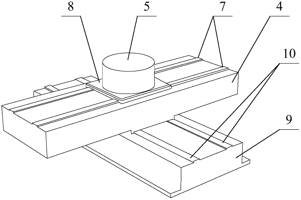
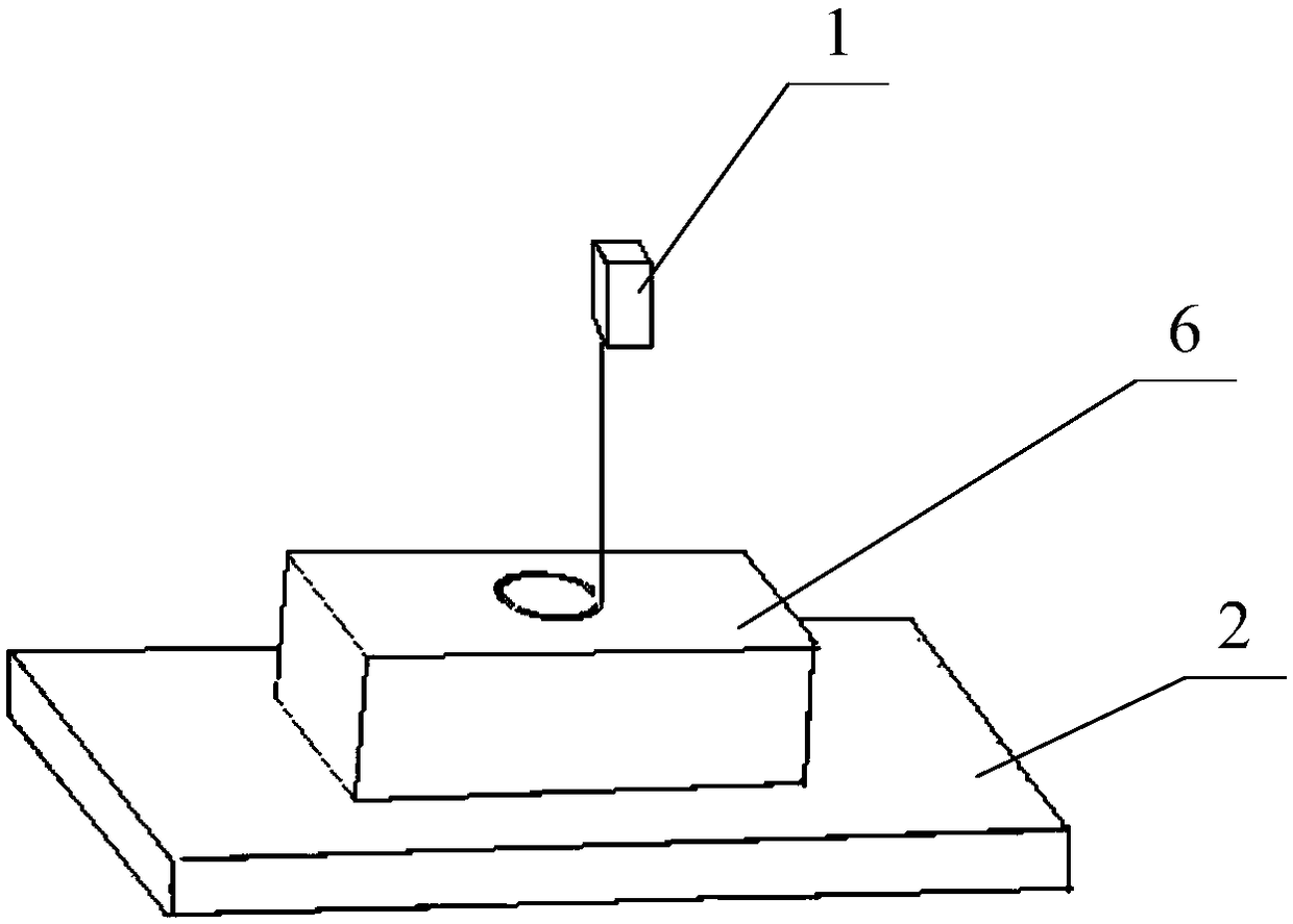
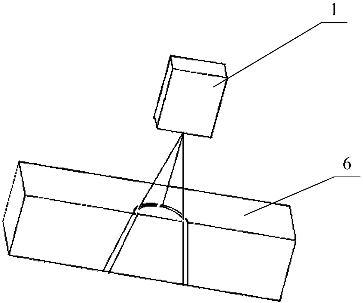
[0025] For the cell microdissection system provided in this specific embodiment, please refer to Figure 1-4 Including: a laser emitting device 1, a macro-micro compound motion platform 2 for placing and driving cell slices 6 to move, and a visual display device 3 connected to the laser emitting device 1 in communication; wherein, the macro-micro compound motion ...


PUM


Abstract

The invention discloses a cell microdissection system including: a laser emitting device, a macro / micro composite movement platform which is used for arranging a cell section and driving the cell section to move, and a visional display apparatus which is communicatively connected to the laser emitting device; wherein the macro / micro composite movement platform includes a first slide board and a rotary member for arranging a cell section and driving the cell section to rotate, thus achieving micro-motion; and the rotary member is connected to the first slide board through a first track and slides on the first track, thus achieving macro-motion of the cell section. According to the invention, by movement of the macro / micro composite movement platform, the system can achieve the macro-motionand micro-motion of the position of the cell section, thereby achieving selection on the cell sections by the laser emitting device, which is unnecessary to move during the process; therefore, microdissection precision and work efficiency are increased, and meanwhile, the process is not related to a galvanometer, so that investment cost is also reduced.

Description

technical field [0001] The invention relates to the field of cell microdissection, and more specifically relates to a cell microdissection system. Background technique [0002] Microdissection (microdissection) technology is a new technology that emerged in the early 1990s, which can cut hundreds or dozens of cells of the same type from tissue sections. Microdissection technology can be used to cut out a single cell group in the tissue for research, to avoid background "pollution" caused by interstitial cells and some inflammatory cells, so as to make the research results accurate and avoid false positive and false negative results. [0003] As far as the prior art is concerned, the microdissection system mainly includes: a laser emitting device 1, a vibrating mirror for adjusting the laser beam, and a visual display device 3 communicated with the laser emitting device 1; when in use, the laser beam is adjusted through the vibrating mirror position to select the cell slice ...

Claims


Application Information

Patent Timeline
IPC IPC(8): G01N1/04G01N1/28
CPCG01N1/04G01N1/28
Inventor 关均铭汤晖詹博羽张桂鑫李嘉龙王伟民陈凯铧高健陈新
Owner GUANGDONG UNIV OF TECH
Why Eureka
Try Eureka