Simple blowing device for automobile wheel hub

A simple technology for automobile wheels, applied in lighting and heating equipment, household refrigeration equipment, household appliances, etc., can solve the problems of affecting product quality, easy to blow and wrinkle the paint layer, waste of manpower, etc., to save manpower, high cooling quality, The effect of improving efficiency

Active Publication Date: 2020-12-25
TIANJIN HAOYAN TECH DEV
View PDF6 Cites 0 Cited by
  • Summary
  • Abstract
  • Description
  • Claims
  • Application Information

AI Technical Summary

Problems solved by technology

[0003] At present, the wheel hub coating and baking paint production line, the temperature of the hub is high when it comes off the line. If it is packaged online, due to the high temperature of the wheel and the soft paint film, it is easy to produce wheel rim indentation and adhesion to po bags, which will affect product quality. Cooling and cooling treatment. The existing wheel hubs are generally operated manually during blowing, cleaning and cooling. When the initial blowing is performed, the temperature of the paint layer is still high. If the blowing force is high, it is easy to blow the paint layer. When blowing air, it is necessary to manually rotate the wheel hub to realize the overall blowing and cooling of the wheel hub, which is a waste of manpower and has low work efficiency. Therefore, we have designed a simple blowing device for automobile wheel hubs to solve the above problems

Method used


Image

  • Simple blowing device for automobile wheel hub
  • Simple blowing device for automobile wheel hub
  • Simple blowing device for automobile wheel hub

Examples


Embodiment Construction

[0020] The following will clearly and completely describe the technical solutions in the embodiments of the present invention with reference to the accompanying drawings in the embodiments of the present invention. Obviously, the described embodiments are only some, not all, embodiments of the present invention.

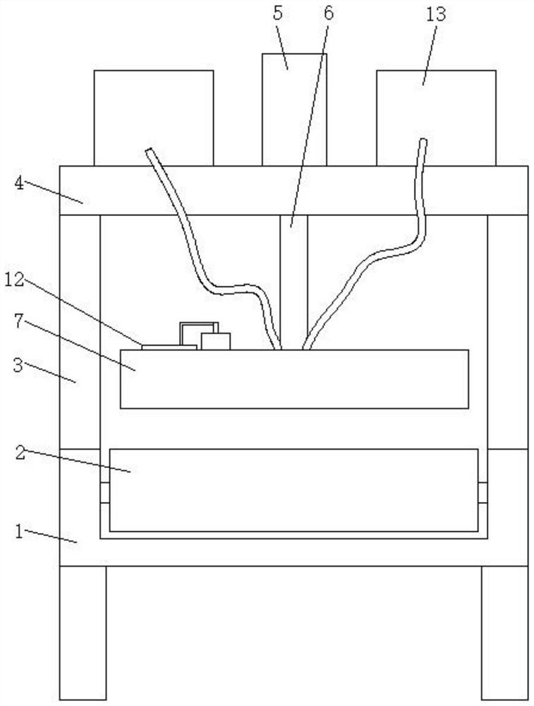
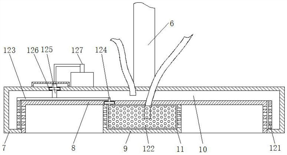
[0021] refer to Figure 1-5 , a simple blowing device for automobile wheels, including a workbench 1, a conveyor belt 2 is provided on the workbench 1, and vertical support rods 3 are arranged on both sides of the conveyor belt 2, and two sets of support rods 3 It is fixed on the workbench 1 by screws, and a top plate 4 is vertically welded on the end of the two groups of support rods 3 far away from the workbench 1, and a cylinder 5 is installed in the center of the side of the top plate 4 away from the support rod 3, and the output end of the cylinder 5 is connected with a lift. The pull rod 6 and the end of the pull rod 6 away from the cylinder 5 are vertically we...


PUM


Abstract

The invention discloses simple air blowing equipment for vehicle hubs. The equipment comprises a worktable; a conveying belt is arranged on the worktable; support rods are vertically arranged on the two sides of the conveying belt; the ends, far from the worktable, of the two sets of support rods are vertically welded with a top plate; a cylinder is mounted in the center of the side, far from thesupport rods, of the top plate; an output end of the cylinder is connected with a lifting rod; the end, far from the cylinder, of the lifting rod is vertically welded with an air blowing cover; a first air cavity is formed between an outer air distribution cylinder and the air blowing cover; a second air cavity is formed between an inner air distribution cylinder and the outer air distribution cylinder; and an adjusting device is arranged between the first air cavity and the second air cavity. When paint-baked hubs are cooled by air blowing, the whole hubs can be covered by using the air blowing cover; the hubs have no need to be manually rotated in air blowing, so that the manpower is saved; air is synchronously blown to the inner and outer sides of the hubs, so that the air blowing cooling efficiency is improved; and meanwhile, the air blowing strength is adjustable, so that the blowing wrinkles of paint baking layers of the hubs can be prevented, and the cooling quality is high.

Description

technical field [0001] The invention relates to the field of automobile wheels, in particular to a simple blowing device for automobile wheels. Background technique [0002] The hub is a barrel-shaped, center-mounted metal part on the axle that supports the tire inside the tire. Also known as rims, steel rims, wheels, and tire bells. There are many types of hubs according to diameter, width, molding method and material. [0003] At present, the wheel hub coating and baking paint production line, the temperature of the hub is high when it comes off the line. If it is packaged online, due to the high temperature of the wheel and the soft paint film, it is easy to produce wheel rim indentation and adhesion to po bags, which will affect product quality. Cooling and cooling treatment. The existing wheel hubs are generally operated manually during blowing, cleaning and cooling. When the initial blowing is performed, the temperature of the paint layer is still high. If the blowin...

Claims


Application Information

Patent Timeline
Patent Type & Authority Patents(China)
IPC IPC(8): F25D1/00
CPCF25D1/00
Inventor 王磊
Owner TIANJIN HAOYAN TECH DEV
Why Eureka
Try Eureka