Wear-resistant cam rotor

A technology of cam rotor and rotor body, applied in rotary piston pump, rotary piston machine, rotary piston/oscillating piston pump components, etc., can solve the problem of wear resistance of wear-resistant materials, damage to rotor and cavity wall , the effect is not ideal, etc., to achieve the effect of reducing the degree of wear and reducing friction

Pending Publication Date: 2018-11-16
奥戈恩(广州)泵业有限公司
View PDF2 Cites 2 Cited by
  • Summary
  • Abstract
  • Description
  • Claims
  • Application Information

AI Technical Summary

Problems solved by technology

[0005] Due to the long-term high-speed rotation of the rotor, it often rubs against the wear-resistant plate and the pump chamber during the process, causing damage between the rotor and the chamber wall. This is to improve the wear resistance of the rotor, but this method relies too much on the wear resistance of the wear-resistant material itself, and its effect is not ideal

Method used


Image

  • Wear-resistant cam rotor
  • Wear-resistant cam rotor
  • Wear-resistant cam rotor

Examples


Embodiment Construction

[0027] The following will clearly and completely describe the technical solutions in the embodiments of the present invention with reference to the accompanying drawings in the embodiments of the present invention. Obviously, the described embodiments are only some, not all, embodiments of the present invention. Based on the embodiments of the present invention, all other embodiments obtained by persons of ordinary skill in the art without creative efforts fall within the protection scope of the present invention.

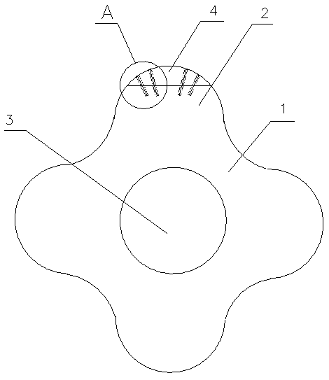
[0028] like figure 1 As shown, a wear-resistant cam rotor includes a rotor body 1 provided with four convex surfaces 2, a rotating shaft core 3 is arranged in the middle of the rotor body 1, and the top surface of the convex surface 2 of the rotor body 1 is planar. The convex surface 2 is detachably provided with an engaging body 4 , and by disposing the detachable engaging body 4 on the convex surface 2 , it is convenient to replace the wear-resistant roller 402 o...


PUM


Abstract

The invention relates to a cam rotor, specifically to a wear-resistant cam rotor. The wear-resistant cam rotor comprises a rotor body equipped with several convex sides. A spindle shaft is arranged atthe center of the rotor body. Engagement bodies are separately arranged on the convex sides. By separately arranging the engagement bodies on the convex sides, when abrasion of a wear resistant stickon the engagement body is large, the engagement bodies can be dismounted, and a brand-new wear resistant stick is placed into a groove, and then a spliceosome A and a spliceosome B are connected andfixed. By arranging the wear resistant stick on the top of the curved surface of the engagement body, friction between the wear resistant stick and a pump cavity can be reduced so as to reduce abrasion of the wear resistant stick. By arranging an elastic device at the bottom of the wear resistant stick, the wear resistant stick can greatly fit the pump cavity. By arranging a waterproof plate and agroove, a fluid can be prevented from entering the inside through a seam; and by arranging a deflector hole on the engagement body, a fluid can be thrown out through the deflector hole by centrifugalforce of the rotor.

Description

technical field [0001] The invention relates to a cam rotor, in particular to a wear-resistant cam rotor. Background technique [0002] The rotor lobe pump is one of the most advanced fluid equipment in the world. Its rotor is fully rubber-coated and has strong wear resistance. The high-precision clearance fit between the rotor and the housing has strong self-priming force and high lift force. The pump is reliable, robust, energy-efficient and can convey a wide range of viscous or particulate-laden media. High efficiency, energy saving, time saving, no need for drainage and pump filling, and can be applied to various complex fluid media. [0003] The lobe rotor (CN201620568347.0) of the existing Chinese patented lobe rotor pump has a wear-resistant material insert (2a, 2b, 2c) fixedly connected to the center top of each lug of the cam rotor through a T-shaped slot. The top end surfaces (3a, 3b, 3c) of the wear-resistant material inserts (2a, 2b, 2c) form arc surfaces consi...

Claims


Application Information

Patent Timeline
Patent Type & Authority Applications(China)
IPC IPC(8): F04C2/08F04C15/00
CPCF04C2/08F04C2/082
Inventor 汤仁亮
Owner 奥戈恩(广州)泵业有限公司
Why Eureka
Try Eureka