


Quick Research
Generate reliable direction feasibility study reports for your R&D in just a few steps.

Technical Q&A
Discover and master advanced knowledge NOW. Basics, ideas, possibilities, all at once.

Find Solutions
As an expert in R&D theories, this can generate solutions to your technical problems instantly.

Evaluate Feasibility
Analyze your overall solution with one click, know your potential R&D risks in advance.

Monitor Landscape
Get weekly tech updates, stay abreast of the latest tech innovations and key insights.
Mechanical automatic grabbing device
A grabbing device and mechanical technology, applied in the direction of conveyor control device, conveyor objects, transportation and packaging, etc., can solve the problems of unreliable grabbing objects, low precision, complex structure, etc., and achieve simple structure and improved Accurate, easy-to-operate results
- Summary
- Abstract
- Description
- Claims
- Application Information
AI Technical Summary
Problems solved by technology
Method used
Image

Examples
Embodiment 1
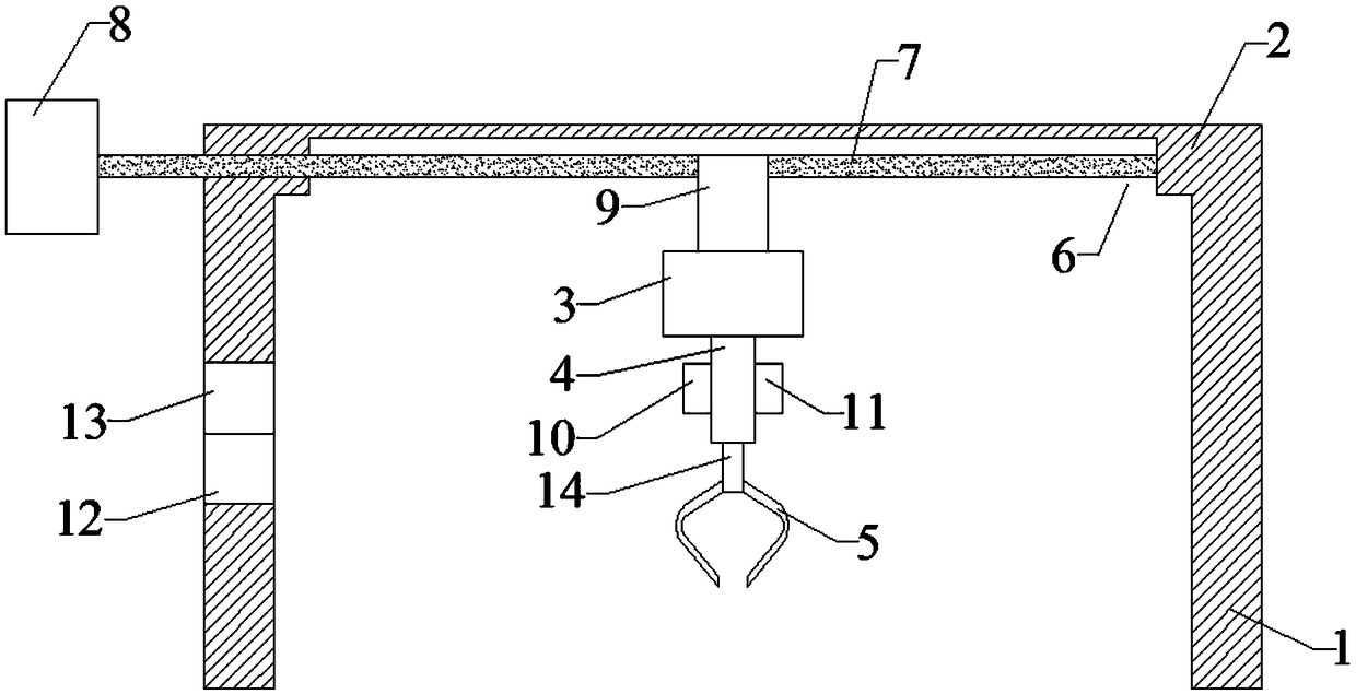
[0018] Such as figure 1 , a mechanical automatic grabbing device, comprising two vertically arranged support columns 1, a support plate 2 and a grabbing device;
[0019] The support plate 2 is horizontally arranged on the upper ends of the two support columns 1, and the support columns 1 are connected. The support column 1 is provided with a controller 12 and a display screen 13, and the display screen 13 is electrically connected with the controller 12. The lower part of the support plate 2 A transverse groove 6 is opened on the surface, and a threaded mandrel 7 is arranged transversely in the indentation 6, and the threaded mandrel 7 extends to the outside of the support plate 2 to connect with the motor 8, which is a three-phase asynchronous motor. The motor 8 is electrically connected with the controller 12, the screw mandrel 7 is connected with a moving block 9 that can move along the screw mandrel 7, the moving block 9 is provided with a threaded hole, the threaded hole ...
Embodiment 2
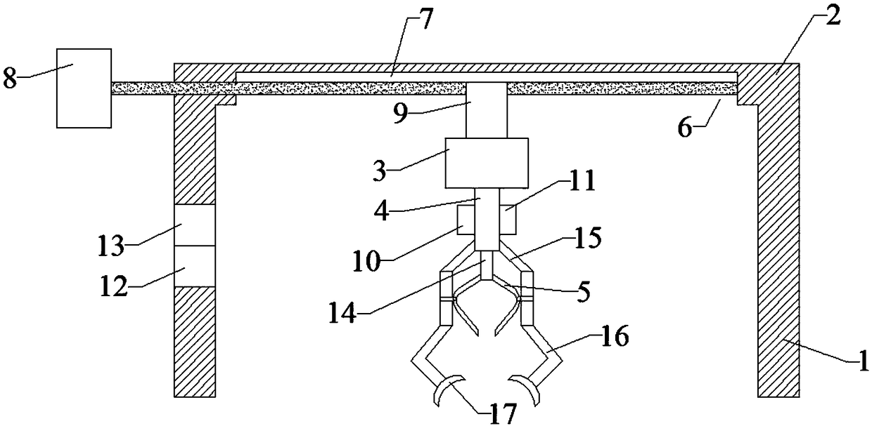
[0023] Such as figure 2 As shown, a mechanical automatic grabbing device includes two vertically arranged support columns 1, a support plate 2 and a grabbing device;
[0024] The support plate 2 is horizontally arranged on the upper ends of the two support columns 1, and the support columns 1 are connected. The support column 1 is provided with a controller 12 and a display screen 13, and the display screen 13 is electrically connected with the controller 12. The lower part of the support plate 2 A transverse groove 6 is opened on the surface, and a threaded mandrel 7 is arranged transversely in the indentation 6, and the threaded mandrel 7 extends to the outside of the support plate 2 to connect with the motor 8, which is a three-phase asynchronous motor. The motor 8 is electrically connected with the controller 12, the screw mandrel 7 is connected with a moving block 9 that can move along the screw mandrel 7, the moving block 9 is provided with a threaded hole, the threaded...
PUM
 Abstract
Description
Claims
Application Information
 - R&D Engineer
- R&D Manager
- IP Professional
- Industry Leading Data Capabilities
- Powerful AI technology
- Patent DNA Extraction
Browse by: Latest US Patents, China's latest patents, Technical Efficacy Thesaurus, Application Domain, Technology Topic, Popular Technical Reports.
© 2024 PatSnap. All rights reserved.Legal|Privacy policy|Modern Slavery Act Transparency Statement|Sitemap|About US| Contact US: help@patsnap.com