
Derusting construction method for cross section of constructional steel I-column

A construction method and cross-section technology, which is applied in the direction of manufacturing tools, grinding workpiece supports, metal processing equipment, etc., can solve the problems of easy rusting of steel plates, influence of coating, and unsatisfactory rust removal effect, etc., to achieve easy to use, The effect of simple structure

Inactive Publication Date: 2018-11-16
冯卫花
View PDF0 Cites 0 Cited by
  • Summary
  • Abstract
  • Description
  • Claims
  • Application Information

AI Technical Summary

Problems solved by technology

Four: Mechanical rust removal, manual rust removal is slow and inefficient, the disadvantage of chemical rust removal is that the rust removal effect cannot be ideal, and it may pollute the environment if it is not handled properly
However, the steel plate after derusting is easy to return to rust, so it must be coated with a special wet derusting coating, which has a great influence on the coating of general performance coatings.
Although the above-mentioned mechanical rust removal methods are more practical, it becomes helpless for the cross-section rust removal of the I-beam that has been poured on the concrete foundation, because it is actually open-air, and the distance between the steel columns is large, and the equipment for rust removal Difficult, the current method is to weld with manual sand paper, this method greatly reduces the original design load strength of the steel column

Method used


Image

  • Derusting construction method for cross section of constructional steel I-column
  • Derusting construction method for cross section of constructional steel I-column
  • Derusting construction method for cross section of constructional steel I-column

Examples


Embodiment

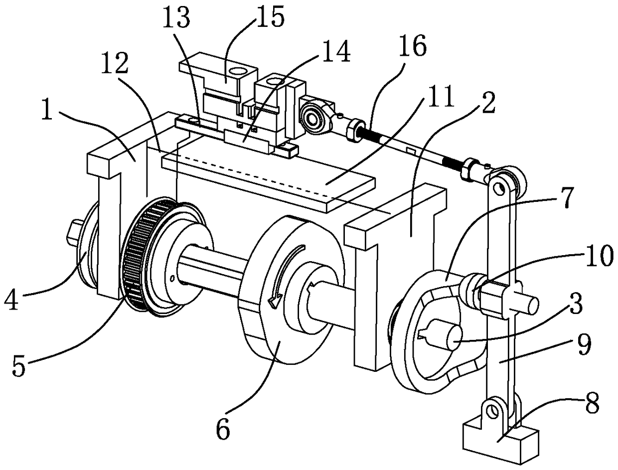
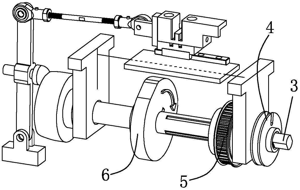
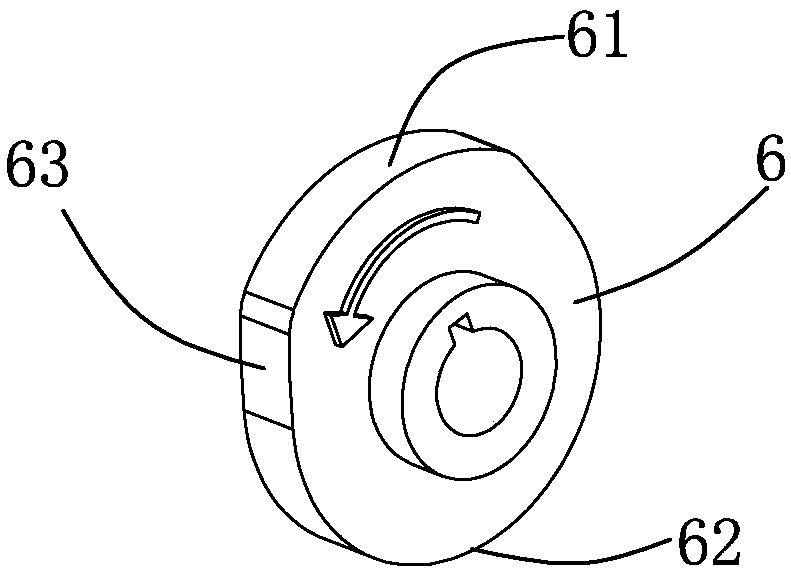
[0026] Embodiment: A construction method for derusting the cross-section of a building I-shaped steel column. Its main structures include: frame block a1, frame block b2, rotating shaft 3, calibration disc 4, crawler disc 5, top disc 6, lug disc 61, Disc disk 62, arc disk 63, displacement disk 7, low ring 71, high ring 72, steep slope ring 73, base block 8, pull rod 9, ball rod 10, top plate 11, through rod 12, slide rail 13, The slider 14, the clamping piece 15, the link 16, the iron brush plate 17, and the rotating shaft 3 successively passes through the calibration plate 4, the frame block a1, the crawler disc 5, the top plate 6, the frame block b2, and the displacement plate 7; The middle positions of the tops of the frame a1 and b2 are slotted, the through-rod 12 runs through the top plate 11, and the two ends of the through-rod 12 are respectively placed in the slots of the frame a1 and the frame b2 ;

[0027] The base block 8 is hinged with one end of the pull rod 9, a...


PUM


Abstract

The invention relates to a derusting construction method for the cross section of a constructional steel I-column. A rotary shaft penetrates through a calibration disc, a frame block a, a track disc,a top disc, a frame block b and a deflection disc in sequence, and slots are formed in the middles of the tops of the frame blocks a and b respectively; a through rod penetrates through a top plate block, and the two tail ends of the through rod are arranged in the slots of the frame blocks a and b respectively; a base block is hinged to one end of a pull rod, a ball screw is fixed to the middle of the pull rod, and the ball end of the ball screw abuts against the vertical end face of the deflection disc. According to the derusting construction method, through linkage of the top disc, the deflection disc and a clamping piece, an iron brush plate can automatically derust the i-section steel according to a preset locus; the technological means that iron brush plates can be classified into five specifications according to different I-steel section grinding fineness degrees is adopted, and it is achieved that welding faces in different shapes can be ground according to different welding requirements; besides, the designed product is simple in structure, and constructors easily get started.

Description

technical field [0001] The invention relates to a construction method for derusting the cross section of a building I-shaped steel column. Background technique [0002] Metal rust removal methods can be divided into four categories: 1: Manual rust removal. Two: chemical rust removal. Three: Ultrasonic derusting. Four: Mechanical rust removal, manual rust removal is slow and inefficient, and the disadvantage of chemical rust removal is that the rust removal effect cannot be ideal, and it may pollute the environment if it is not handled properly. The choice of rust removal method should be based on various factors such as environment and effect. It is unscientific to say that a certain method is better than bad. Mechanical derusting is generally divided into four types: shot blasting, electric derusting, sandblasting and high-pressure water abrasive derusting. 1. Shot blasting rust removal, shot blasting rust removal is to use the high-speed rotating impeller to throw abra...

Claims


Application Information

Patent Timeline
Patent Type & Authority Applications(China)
IPC IPC(8): B24B27/033B24B47/12B24B41/02
CPCB24B27/033B24B41/02B24B41/04B24B41/06B24B47/12B24B47/16B24B47/20
Inventor 冯卫花
Owner 冯卫花
Learn More