
A repair method for anti-roll torsion bar shaft after galvanic corrosion

An anti-roll torsion bar and galvanic corrosion technology, which is applied in the field of rework, can solve the problems of no identical or similar patent documents, high scrap rate of anti-roll torsion bar devices, high maintenance costs, etc., and achieve improved grinding Quality, increase the contact area, reduce the effect of work intensity

Active Publication Date: 2021-04-16
ZHUZHOU TIMES NEW MATERIALS TECH
View PDF9 Cites 0 Cited by
  • Summary
  • Abstract
  • Description
  • Claims
  • Application Information

AI Technical Summary

Problems solved by technology

Due to the high scrap rate of the anti-roll torsion bar device, the maintenance cost of this product is high, and the anti-roll torsion bar device on some rail vehicles is developed locally on the basis of foreign products, and most of its structure The foreign prototype structure is used, and it is difficult to improve. In addition, in recent years, the anti-roll torsion bar device on some rail vehicles has an annual output value of about 100 million yuan, and the output value is large. very considerable, therefore, the solution to this problem is particularly urgent and important
[0005] After searching, no patent documents identical or similar to this application have been found

Method used


Image

  • A repair method for anti-roll torsion bar shaft after galvanic corrosion
  • A repair method for anti-roll torsion bar shaft after galvanic corrosion
  • A repair method for anti-roll torsion bar shaft after galvanic corrosion

Examples


Embodiment 1

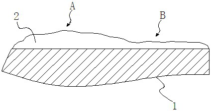
[0045] Example 1: A repair method for the anti-rolling torsion bar shaft after galvanic corrosion, which is to restore the corroded shaft end to the service requirements by spraying a coating on the shaft end of the anti-rolling torsion bar shaft Size, so as to repair the anti-roll torsion bar shaft after galvanic corrosion. After galvanic corrosion occurs, the end of the torsion bar shaft will be corroded, so that the actual size of the shaft end cannot reach the size required for use, resulting in scrapping. In this embodiment, by spraying a coating on the shaft end, the coating is used to restore the size of the shaft end after galvanic corrosion to the size required for use, so that the rusted torsion bar shaft can be repaired and the torsion bar can be extended. The service life of the shaft is reduced, the scrap rate of the torsion bar shaft is reduced, and the cost of use is reduced.

[0046] The step of described spray coating is:

[0047] a. Perform surface treatmen...

Embodiment 2

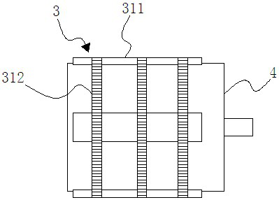
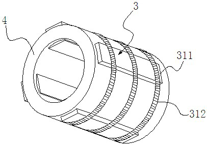
[0068] Embodiment 2: Compared with Embodiment 1, the difference is: the grinding step is:

[0069] S1, first extend the coated shaft end into the inside of the grinding sleeve;

[0070] S2, placing multiple grinding blocks in multiple limiting grooves;

[0071] S3, then wind the spring one on the outside of the grinding sleeve with multiple grinding blocks, so that the spring one is in contact with the other end of the multiple grinding blocks to elastically compress the multiple grinding blocks on the multiple grinding blocks One end of a plurality of grinding blocks protrudes into the inside of the grinding sleeve to contact the coating on the end of the shaft, and then rotates the grinding sleeve for grinding.

Embodiment 3

[0072] Embodiment 3: as Figure 6 As shown, compared with Embodiment 1, the difference lies in that an arc-shaped inner groove 6 is formed on the upper base of the trapezoidal grinding block 311 . This can increase the contact area with the coating, thereby further improving the grinding quality.


PUM

PropertyMeasurementUnit
electrical resistanceaaaaaaaaaa

Abstract

The invention discloses a method for repairing after galvanic corrosion of an anti-rolling torsion bar shaft, which is to restore the corroded shaft end to use requirements by spraying a coating on the shaft end of the anti-rolling torsion bar shaft Size, so as to repair the anti-roll torsion bar shaft after galvanic corrosion. The invention can repair the corroded torsion bar shaft, prolongs the service life of the torsion bar shaft, reduces the scrap rate of the torsion bar shaft and thus reduces the use cost.

Description

technical field [0001] The invention relates to a repair method, in particular to a repair method after anti-rolling torsion bar shaft galvanic couple corrosion. Background technique [0002] When a rail vehicle passes through curves and turnouts at high speed or stops on a curve with superelevation, the roll increases significantly, and the load on one side of the wheel is reduced. When encountering strong lateral winds, it may even overturn and become unstable, reducing safety. It is necessary to increase the roll stiffness of the vehicle to limit its roll angle, but it cannot affect the vibration characteristics of the vehicle such as ups and downs, yaw, shake head, telescopic and nod. [0003] The anti-roll torsion bar component device is installed on the rail transit vehicle. When the rail vehicle is rolling, the torsion bar shaft is twisted and deformed, and together with other components, it provides the roll stiffness required for the safe operation of the vehicle to...

Claims


Application Information

Patent Timeline
Patent Type & Authority Patents(China)
IPC IPC(8): B23P6/00
CPCB23P6/00
Inventor 杜方孟王亚平范湘盛超包胜军韩喜龙
Owner ZHUZHOU TIMES NEW MATERIALS TECH
Learn More