Water dispenser facilitating water change in factory
A water dispenser and factory technology, applied in applications, home appliances, kitchen appliances, etc., can solve problems such as easy falling down, accidental accidents in buckets, slipping of hands when buckets, etc., and achieve the effect of increasing friction and fixing stability.
- Summary
- Abstract
- Description
- Claims
- Application Information
AI Technical Summary
Problems solved by technology
Method used
Image

Examples
Embodiment 1
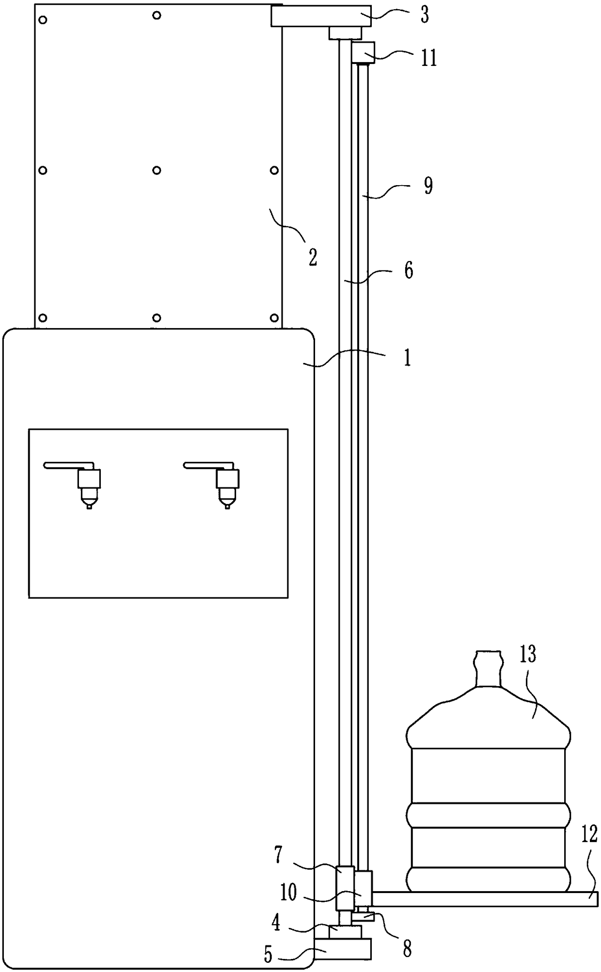
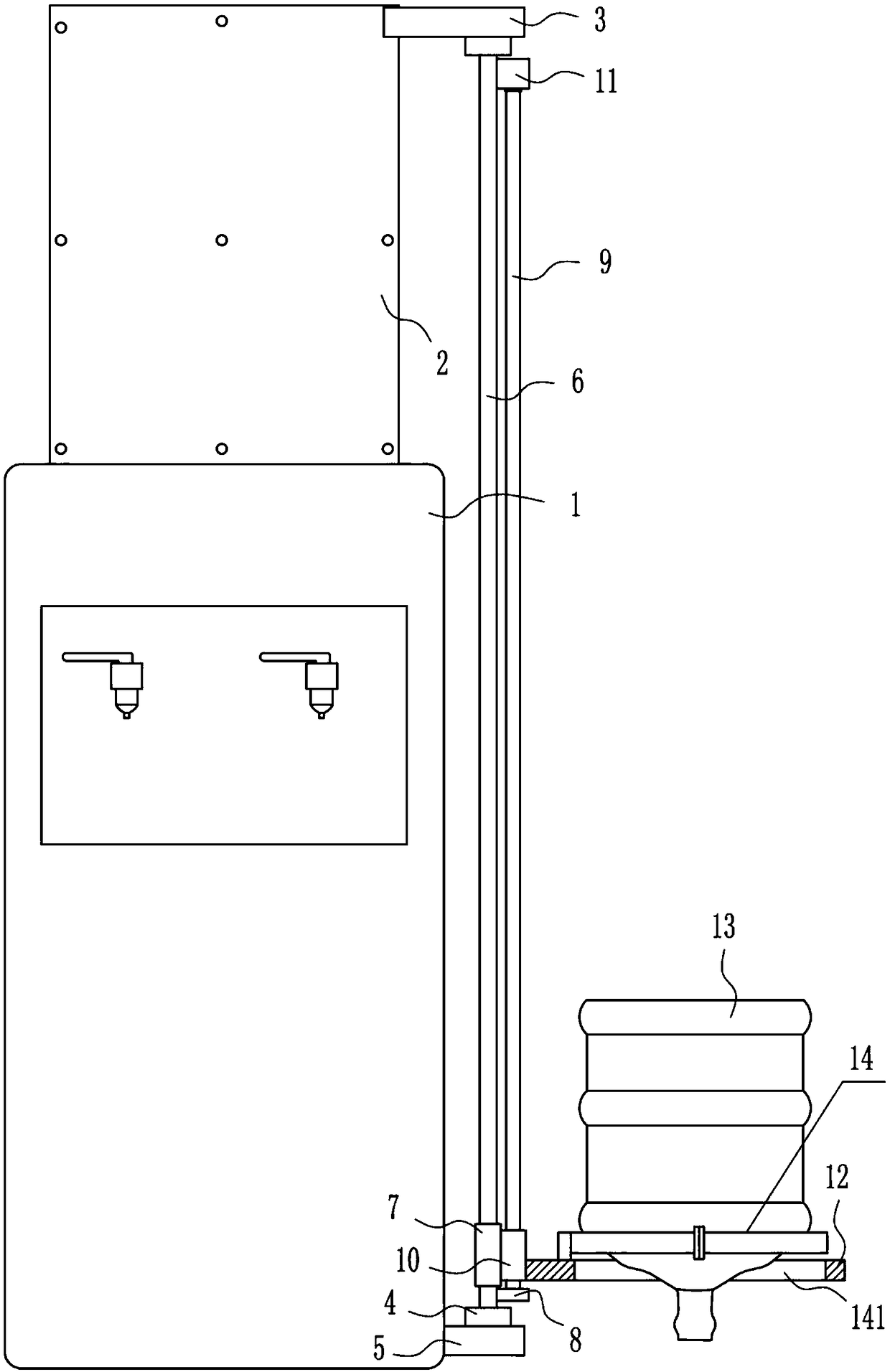
[0021] A factory water dispenser that is easy to change water, such as Figure 1-4 As shown, it includes a water dispenser body 1, a vertical plate 2, a horizontal plate 3, a first bearing seat 4, a fixed plate 5, a rotating rod 6, a sliding sleeve 7, a second bearing seat 8, a screw rod 9, a nut 10, the first A motor 11 and a placement plate 12, a vertical plate 2 is installed on the rear side of the top of the water dispenser body 1, a horizontal plate 3 is installed on the upper right side of the front side of the vertical plate 2, and a fixed plate 5 is installed on the lower right side of the water dispenser body 1. The first bearing seat 4 is installed in the middle of the top of the plate 5 and the right side of the bottom of the horizontal plate 3. A rotating rod 6 is connected between the first bearing seats 4 on the upper and lower sides. The rotating rod 6 is provided with a sliding sleeve 7. A second bearing seat 8 is installed on the lower part of the side, and a ...
Embodiment 2
[0023] A factory water dispenser that is easy to change water, such as Figure 1-4As shown, it includes a water dispenser body 1, a vertical plate 2, a horizontal plate 3, a first bearing seat 4, a fixed plate 5, a rotating rod 6, a sliding sleeve 7, a second bearing seat 8, a screw rod 9, a nut 10, the first A motor 11 and a placement plate 12, a vertical plate 2 is installed on the rear side of the top of the water dispenser body 1, a horizontal plate 3 is installed on the upper right side of the front side of the vertical plate 2, and a fixed plate 5 is installed on the lower right side of the water dispenser body 1. The first bearing seat 4 is installed in the middle of the top of the plate 5 and the right side of the bottom of the horizontal plate 3. A rotating rod 6 is connected between the first bearing seats 4 on the upper and lower sides. The rotating rod 6 is provided with a sliding sleeve 7. A second bearing seat 8 is installed on the lower part of the side, and a s...
Embodiment 3
[0026] A factory water dispenser that is easy to change water, such as Figure 1-4 As shown, it includes a water dispenser body 1, a vertical plate 2, a horizontal plate 3, a first bearing seat 4, a fixed plate 5, a rotating rod 6, a sliding sleeve 7, a second bearing seat 8, a screw rod 9, a nut 10, the first A motor 11 and a placement plate 12, a vertical plate 2 is installed on the rear side of the top of the water dispenser body 1, a horizontal plate 3 is installed on the upper right side of the front side of the vertical plate 2, and a fixed plate 5 is installed on the lower right side of the water dispenser body 1. The first bearing seat 4 is installed in the middle of the top of the plate 5 and the right side of the bottom of the horizontal plate 3. A rotating rod 6 is connected between the first bearing seats 4 on the upper and lower sides. The rotating rod 6 is provided with a sliding sleeve 7. A second bearing seat 8 is installed on the lower part of the side, and a ...
PUM
 Abstract
Description
Claims
Application Information
 - R&D
- Intellectual Property
- Life Sciences
- Materials
- Tech Scout
- Unparalleled Data Quality
- Higher Quality Content
- 60% Fewer Hallucinations
Browse by: Latest US Patents, China's latest patents, Technical Efficacy Thesaurus, Application Domain, Technology Topic, Popular Technical Reports.
© 2025 PatSnap. All rights reserved.Legal|Privacy policy|Modern Slavery Act Transparency Statement|Sitemap|About US| Contact US: help@patsnap.com