
Method for prolonging service life of motor

A technology of life and motor shaft, applied in the direction of electromechanical devices, electrical components, mechanical equipment, etc., can solve the problems of poor heat dissipation at the center of the motor shaft, shortening the service life of the motor, time-consuming and laborious motor maintenance, etc., to reduce resistance and improve use. Efficiency and easy installation and disassembly

Active Publication Date: 2018-11-13
SHANXI ELECTRIC MOTOR MANUFACTURING CO LTD
View PDF4 Cites 6 Cited by
  • Summary
  • Abstract
  • Description
  • Claims
  • Application Information

AI Technical Summary

Problems solved by technology

[0003] Motor (English: Electric machinery, commonly known as "motor") refers to an electromagnetic device that realizes electric energy conversion or transmission according to the law of electromagnetic induction. The service life of the motor is greatly affected by the service life of the bearing. When the bearing is damaged, if it is not Timely replacement will greatly reduce the service life of the motor, and the maintenance of the motor is mostly time-consuming and laborious, which seriously affects the actual production of the enterprise.
At the same time, the motor will generate a lot of heat during operation, which will cause great damage to the motor. The existing method is to install a fan on the motor shaft to force heat dissipation through the fan. However, this method will not only reduce the actual output power of the motor, Moreover, the heat dissipation effect at the center of the motor shaft is poor, which greatly reduces the service life of the motor

Method used


Image

  • Method for prolonging service life of motor
  • Method for prolonging service life of motor
  • Method for prolonging service life of motor

Examples


Embodiment Construction

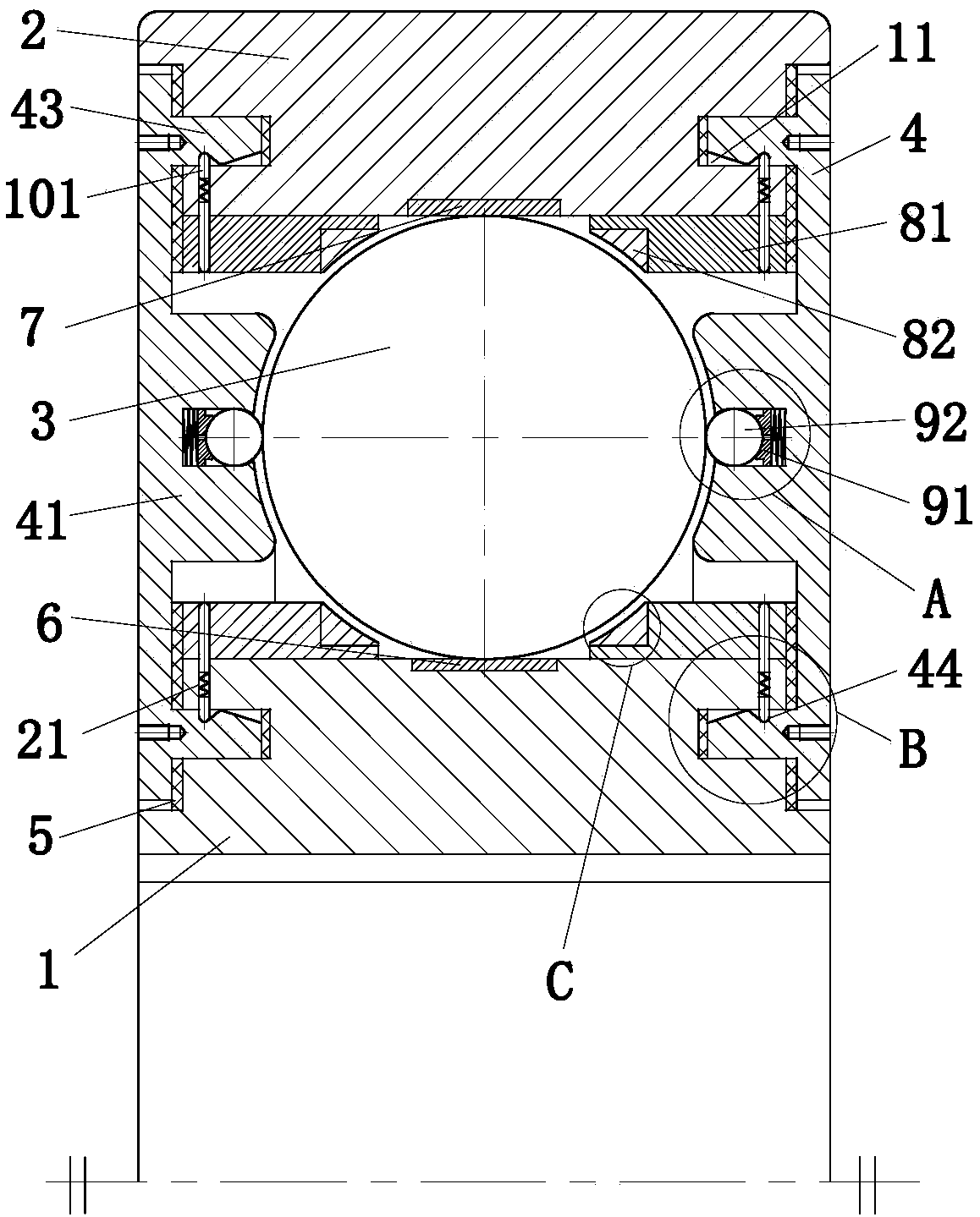
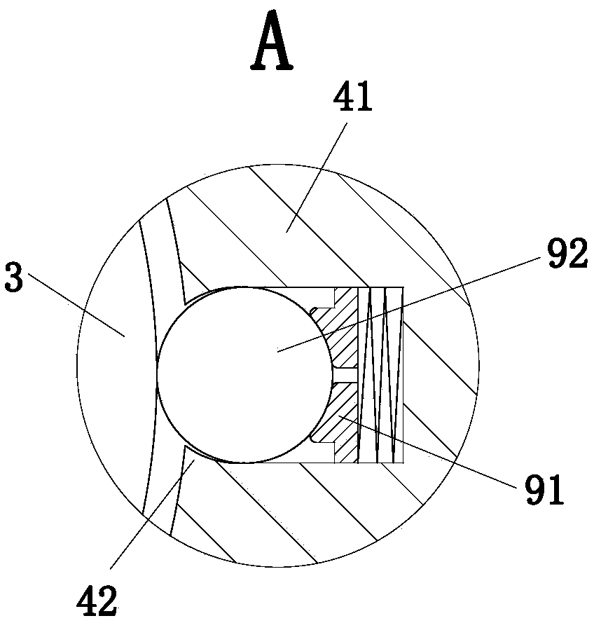
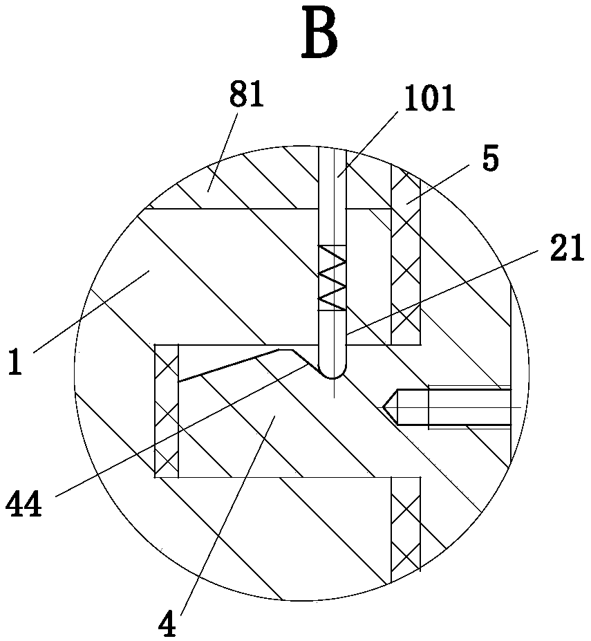
[0021] use Figure 1-Figure 4 The structure of the bearing of the present invention will be explained as follows.

[0022] Such as figure 1 Shown, a kind of method of improving motor service life described in the present invention, this method comprises the following steps:

[0023] S1, the motor shaft is connected to the motor casing through a sealed bearing;

[0024] S2, on the basis of S1, an axial through hole is provided on the motor shaft along the axial coaxial direction, a radial through hole connected with the axial through hole is provided along the radial direction of the motor shaft, the axial through hole and the radial through hole The holes can dissipate the heat inside the motor;

[0025] The sealed bearing adopted in the above method includes an inner ring 1, an outer ring 2, a ball 3 and a sealing end cap 4; A chute 21 is provided, and the chute 21 of the outer ring 2 communicates with the annular groove 11 of the outer ring 2; the inner ring 1 is also pr...


PUM


Abstract

The invention belongs to the technical field of motors, and particularly relates to a method for prolonging the service life of a motor. A sealing bearing adopted in the method comprises an inner ring, an outer ring, a ball and sealing end covers; annular grooves are formed in the two end surfaces of the outer ring and the inner ring respectively, and the ball is located between the inner ring andthe outer ring; two annular protrusions are coaxially arranged on one end planes of the sealing end covers, and the sealing end covers are mounted on the left and right end planes of the inner ring and the outer ring through the annular protrusions and the annular grooves of the inner ring and the outer ring; a contact inner ring and a contact outer ring are arranged at the positions, in contactwith the ball, of the inner ring and the outer ring respectively, and limiting rings are arranged on the inner ring and the outer ring respectively; and an annular boss is arranged at the part, located between the inner ring and the outer ring, of each sealing end cover; and the part, in contact with the roll, of each annular boss is set to be arc-shaped. By virtue of the sealing bearing adopted in the method, resistance caused by the bearing to the motor can be reduced, so that the using efficiency of the motor is improved.

Description

technical field [0001] The invention belongs to the technical field of electric motors, and specifically relates to a method for improving the service life of electric motors. Background technique [0002] During the use of the bearing, harmful substances such as dust, moisture, and foreign matter can easily invade the interior of the bearing or cause the internal lubricant to leak when the bearing rotates, which greatly reduces the lubrication performance of the bearing and reduces the service life of the bearing. The traditional bearing seal is to install the bearing sealing ring through the sealing groove of the outer ring of the bearing. Because the sealing groove of the bearing outer ring and the bearing sealing ring are not tightly matched, when the user uses the bearing, in some cases, the working environment is poor and the bearing is soaked in liquid. If it is immersed in the place, the grease in the bearing cavity will deteriorate, the lubricating performance will...

Claims


Application Information

Patent Timeline
IPC IPC(8): H02K7/08H02K9/00F16C33/78F16C33/38F16C33/58
Inventor 尹苑苑
Owner SHANXI ELECTRIC MOTOR MANUFACTURING CO LTD
Learn More