Electric-control liquid crystal objective and ten-thousand-level amplification factor optical microscope utilizing same

A magnification and liquid crystal technology, which is applied in the field of 10,000-level magnification optical microscope, can solve the problems of sample surface topography and structure pollution, destruction of active biological tissue, high cost of use, etc., and achieve low price, flexible and convenient use, and low production cost Effect

Active Publication Date: 2018-11-13
NANJING OPY ELECTRONICS TECH CO LTD
View PDF6 Cites 6 Cited by
  • Summary
  • Abstract
  • Description
  • Claims
  • Application Information

AI Technical Summary

Problems solved by technology

[0004] In view of the above defects or improvement needs of the prior art, the present invention provides an electronically controlled liquid crystal objective lens and a 10,000-level magnification optical microscope using it. As the objective lens of the micro-imaging system, the micro-mirror solves the technical problem of poor micro-imaging and observation capabilities of existing optical microscopes for samples with sub-micron or even nano-sized structures or active biological tissues with strong scattering characteristics. The technical problems of high cost, the pollution of the surface topography of the sample, the technical problems of high complexity, and the damage or even destruction of the activity placed in the high vacuum environment due to the use of electronic contact microscopic imaging observation Technical Issues of Biological Organization

Method used


Image

  • Electric-control liquid crystal objective and ten-thousand-level amplification factor optical microscope utilizing same
  • Electric-control liquid crystal objective and ten-thousand-level amplification factor optical microscope utilizing same
  • Electric-control liquid crystal objective and ten-thousand-level amplification factor optical microscope utilizing same

Examples


Embodiment Construction

[0039] In order to make the object, technical solution and advantages of the present invention clearer, the present invention will be further described in detail below in conjunction with the accompanying drawings and embodiments. It should be understood that the specific embodiments described here are only used to explain the present invention, not to limit the present invention. In addition, the technical features involved in the various embodiments of the present invention described below can be combined with each other as long as they do not constitute a conflict with each other.
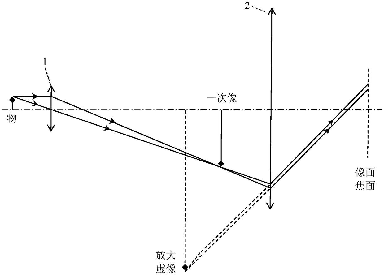
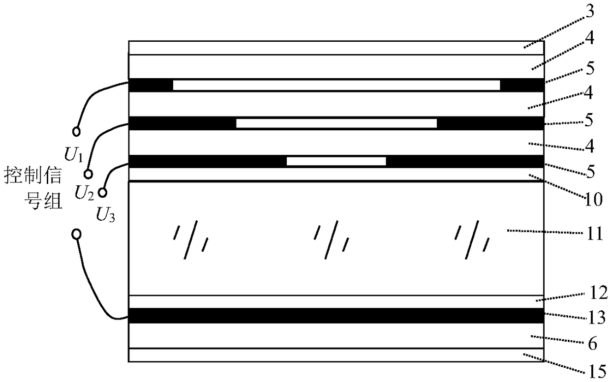
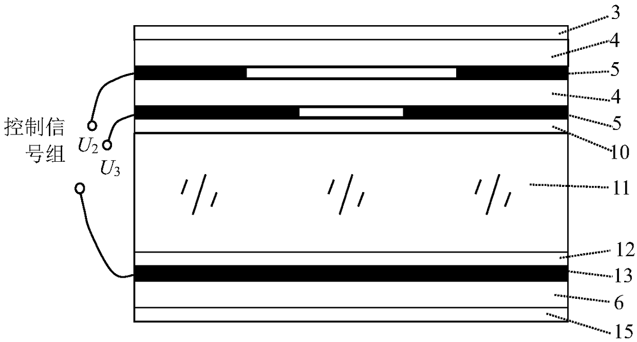
[0040] The basic idea of ​​the present invention is that by adopting the electronically controlled liquid crystal micromirror with electrically adjustable aperture and focal length as the objective lens of the microscopic imaging system, the electronic control of the electronically controlled liquid crystal objective lens is increased on the basis of basically maintaining the structural character...


PUM

PropertyMeasurementUnit
thicknessaaaaaaaaaa
thicknessaaaaaaaaaa
thicknessaaaaaaaaaa

Abstract

The invention discloses an electric-control liquid crystal objective and a ten-thousand-level amplification factor optical microscope utilizing the same. The electric-control liquid crystal objectivecomprises a first antireflection film, at least two annular pattern electrodes, at least one first substrate, a first PI orientation layer, a liquid crystal layer, a second PI orientation layer, a public electrode, a second substrate and a second antireflection film which are arranged in parallel, wherein the centers of the annular pattern electrodes are overlapped in the vertical direction, the outer diameters of all the annular pattern electrodes are the same, and the inner diameters of the annular pattern electrodes gradually decrease from top to bottom; the first substrate is arranged between two adjacent annular pattern electrodes; the first PI orientation layer is arranged at the lower part of the lower annular pattern electrode; and the public electrode is arranged between the second PI orientation layer and the second substrate, and the center of the public electrode is overlapped with the centers of the annular pattern electrodes in the vertical direction. According to the electric-control liquid crystal objective, the technical problem that an existing optical microscope has poor microimaging and observing capacities to samples with submicron even nanometer structures oractive biological tissues with strong scattering feature is solved.

Description

technical field [0001] The invention belongs to the technical field of optical microscopic imaging observation and precision measurement, and more specifically relates to an electronically controlled liquid crystal objective lens and a 10,000-level magnification optical microscope using the same. Background technique [0002] So far, the maximum magnification of conventional optical microscopes is between 2,000 times and 3,000 times. The typical size of the smallest structure that can be clearly resolved is on the scale of several microns, and the imaging depth of field is on the order of hundreds of nanometers. During the working process of the optical microscope, it selects targets at different object distances or depths with micron-level measurement precision through the highest manual or mechanical focusing method with micron-level movement precision, performs microscopic imaging observation and measurement operations, and uses Change the way of objective lens to obtain ...

Claims


Application Information

Patent Timeline
Patent Type & Authority Applications(China)
IPC IPC(8): G02F1/1343G02F1/1337G02F1/1335G02F1/1333G02F1/13G02B21/02
CPCG02B21/025G02F1/1313G02F1/1333G02F1/1335G02F1/1337G02F1/1343G02F1/133302
Inventor 张汤安苏张新宇
Owner NANJING OPY ELECTRONICS TECH CO LTD
Why Eureka
Try Eureka