Visual detection system for line overcurrent faults

An overcurrent fault detection system technology, which is applied in the direction of fault location and fault detection according to the conductor type, can solve the problems of heavy investigation workload, few installations, and power-off installation required for installation, so as to improve the response speed of disposal and reduce the Check work and improve work efficiency

Inactive Publication Date: 2018-11-13
SHANDONG SENTER ELECTRONICS
View PDF0 Cites 0 Cited by
  • Summary
  • Abstract
  • Description
  • Claims
  • Application Information

AI Technical Summary

Problems solved by technology

[0002] Existing fault detection devices can only detect that a fault has occurred, or how far the fault occurs from the substation, and there is no supporting camera equipment to record it, but the existing transmission line monitoring device (timed photographing and monitoring Video) cannot take pictures when a fault occurs, capture the cause of the fault and obtain evidence, or a large number of video files, the investigation workload is quite large
At the same time, the current transmission line overcurrent fault detection device belongs to the traveling wave principle. Although the approximate location of the fault point can be obtained, it can only be located. For example, the contact line fault of the engineering vehicle cannot be known in time, and only the traveling wave positioning device can obtain the fault. The location, and then send people to patrol and check to find out. If the personnel do not arrive on the scene in time, it will be difficult to complete the photo collection
[0003] Moreover, the general traveling wave fault location device is expensive and needs to be installed in a power failure. If it is on some non-important lines, it is rarely installed in order to save costs.
And the installation needs to be powered off
The weight of the device will be relatively heavy, and the installation will be more laborious. Long-term weight and wire vibration will also cause a little damage to the transmission line

Method used


Image

  • Visual detection system for line overcurrent faults

Examples


Embodiment 1

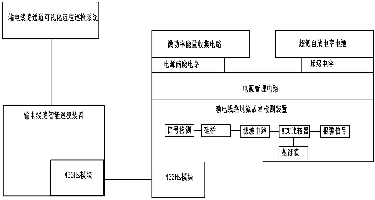
[0017] With reference to the drawings in the description, the purpose of the present invention is to provide a visualization-based line overcurrent fault detection system, which is characterized in that it includes a transmission line intelligent patrol device and a transmission line overcurrent fault detection device, and the transmission line overcurrent fault detection The device acquires energy through current induction, and stores energy through supercapacitors and batteries; the transmission line overcurrent fault detection device is connected to the transmission line intelligent inspection device through wireless signals, and the transmission line intelligent inspection device is uploaded to The background of the transmission line channel visualization remote inspection system, the transmission line channel visualization remote inspection system remotely links the intelligent inspection device on the entire line to take pictures, completes the entire line photoshoot, and ...


PUM


Abstract

The invention discloses a visual detection system for line overcurrent faults. The system comprises a power transmission line intelligent inspection device and a power transmission line overcurrent fault detection device, wherein the power transmission line overcurrent fault detection device acquires energy in a current induction mode and stores energy through a super capacitor and a battery; thepower transmission line overcurrent fault detection device is connected with the power transmission line intelligent inspection device through a wireless signal, the power transmission line intelligent inspection device uploads the signal to the background of a visual remote inspection system of a power transmission line channel through a 4G channel, the visual remote inspection system of the power transmission line channel is in remote linkage with an intelligent inspection device on the whole line for photographing, the whole line is photographed, and alarm is made in the background. The inspection mode and the evidence collection mode of the current power transmission line under certain overcurrent faults can be improved, and the faults can be captured, photographed and uploaded in time.

Description

technical field [0001] The invention relates to a visualization-based line overcurrent fault detection system, which belongs to the field of online monitoring equipment for transmission lines. Background technique [0002] Existing fault detection devices can only detect that a fault has occurred, or how far the fault occurs from the substation, and there is no supporting camera equipment to record it, but the existing transmission line monitoring device (timed photographing and monitoring Video) cannot take pictures when a fault occurs, capture the cause of the fault and obtain evidence, or have a large number of video files, and the investigation workload is quite large. At the same time, the current transmission line overcurrent fault detection device belongs to the traveling wave principle. Although the approximate location of the fault point can be obtained, it can only be located. For example, the contact line fault of the engineering vehicle cannot be known in time, a...

Claims


Application Information

Patent Timeline
Patent Type & Authority Applications(China)
IPC IPC(8): G01R31/08
CPCG01R31/085
Inventor 蔡富东王成李在学朱荣俊王清鹏付栋李文豪崔利
Owner SHANDONG SENTER ELECTRONICS
Why Eureka
Try Eureka