Charge gun test device and system
A test device, charging gun technology, applied in the field of circuits, can solve the problems of poor compatibility and scalability, low degree of automation, etc.
- Summary
- Abstract
- Description
- Claims
- Application Information
AI Technical Summary
Problems solved by technology
Method used
Image
Examples
Embodiment 1
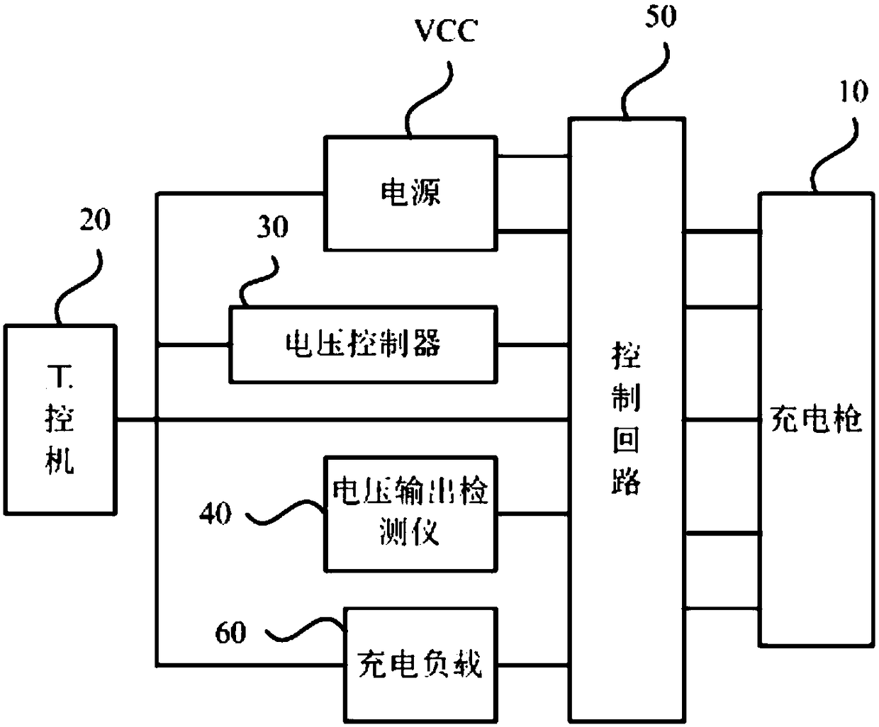
[0034] The charging gun testing device provided in this embodiment can be applied to the application scenario of charging the charging gun and testing its own contactor. figure 1 It is a schematic structural diagram of a charging gun testing device provided in Embodiment 1 of the present invention. see figure 1 As shown, the charging gun testing device provided in this embodiment includes: a power supply VCC, an industrial computer 20 , a voltage controller 30 , a voltage output detector 40 , a control circuit 50 , and a charging load 60 .
[0035] Wherein, the power supply VCC is connected with the power signal input end of the charging gun 10, and is used to provide the electrical signal for the charging gun 10; the control end of the control loop 50 is connected with the control end of the industrial computer 20, and the output end of the control loop 50 is connected with the charging gun The control terminal of 10 is connected to receive the control signal sent by the ind...
Embodiment 2
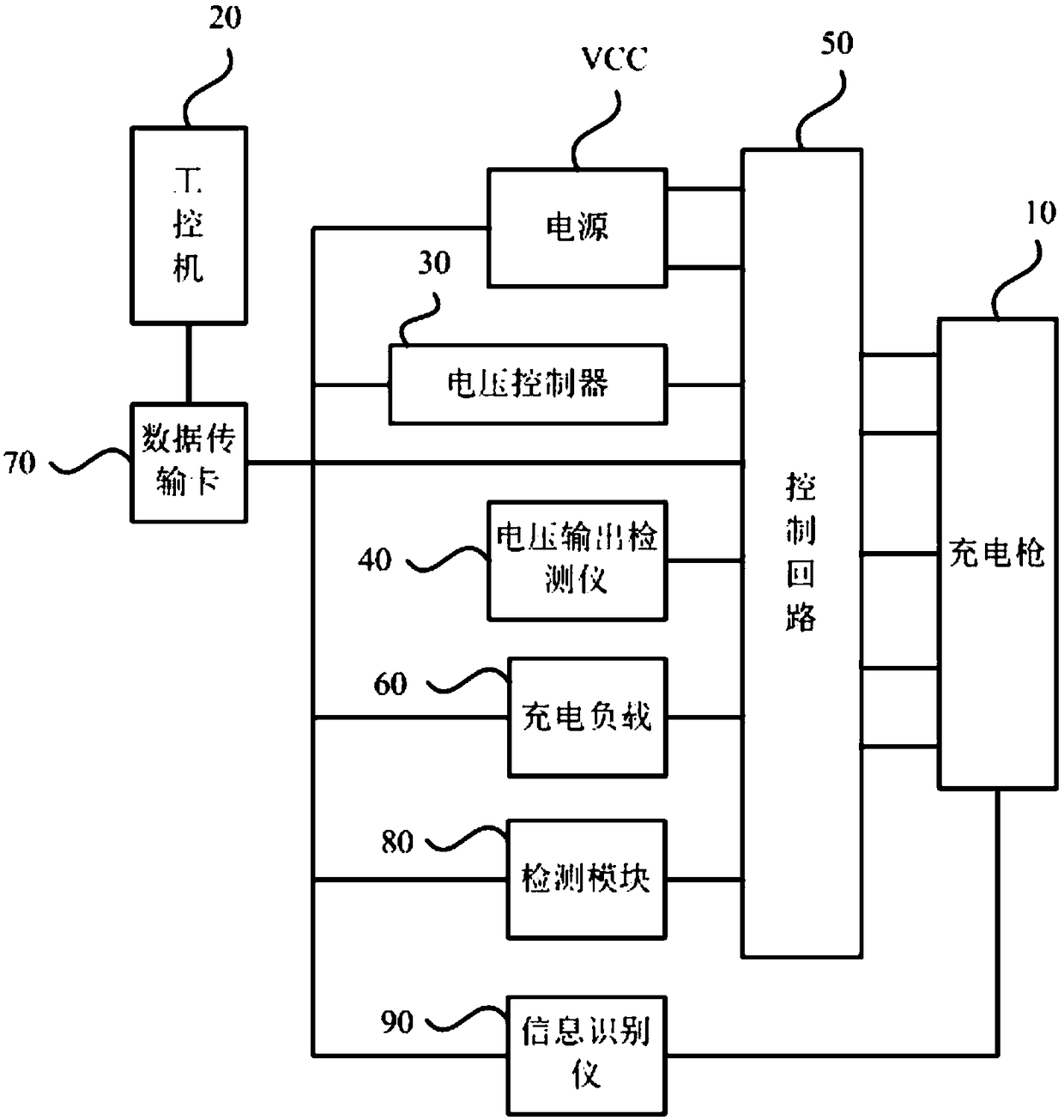
[0045] This embodiment is optimized on the basis of the above embodiments, and a data transmission card is preferably added on the basis of the above embodiments, and the data transmission card can perform data transmission between the industrial computer and other test hardware. figure 2 It is a schematic structural diagram of a charging gun testing device provided in Embodiment 2 of the present invention. like figure 2 As shown, the charging gun testing device provided in this embodiment includes: a power supply VCC, an industrial computer 20 , a voltage controller 30 , a voltage output detector 40 , a control circuit 50 , a charging load 60 , and a data transmission card 70 .
[0046] Among them, the data transmission card 70 is used to connect the control terminal of the industrial computer 20 with the control terminal of the voltage controller 30, the control terminal of the voltage output detector 40, the control terminal of the control circuit 50, and the control term...
Embodiment 3
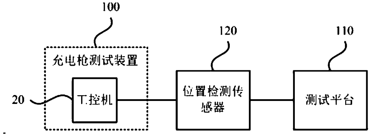
[0054] This embodiment provides a charging gun testing system, which can conduct a comprehensive test on the charging gun. image 3 It is a schematic structural diagram of a charging gun testing system provided by an embodiment of the present invention. like image 3 As shown, the charging gun testing system provided by the embodiment of the present invention includes the charging gun testing device 100 provided by the embodiment of the present invention, a test platform 110 and a position detection sensor 120 .
[0055] Wherein, the position detection sensor 120 is configured on the test platform 110, and the output end of the position detection sensor 120 is connected with the input end of the industrial computer 20 in the charging gun testing device 100, for detecting whether the charging gun on the test platform 110 is in place, and The position detection signal is transmitted to the industrial computer 20; the industrial computer 20 sends a corresponding control signal a...
PUM
 Abstract
Description
Claims
Application Information
 - R&D
- Intellectual Property
- Life Sciences
- Materials
- Tech Scout
- Unparalleled Data Quality
- Higher Quality Content
- 60% Fewer Hallucinations
Browse by: Latest US Patents, China's latest patents, Technical Efficacy Thesaurus, Application Domain, Technology Topic, Popular Technical Reports.
© 2025 PatSnap. All rights reserved.Legal|Privacy policy|Modern Slavery Act Transparency Statement|Sitemap|About US| Contact US: help@patsnap.com


