
Pin-inserted LED lamp strip

A technology of LED strips and LED wicks, which is applied in the parts of lighting devices, semiconductor devices of light-emitting elements, cooling/heating devices of lighting devices, etc. problems such as the strength of the strip structure, to achieve the effect of improving structural stability, convenient fixing and structural stability

Pending Publication Date: 2018-11-13
江苏运鸿辉电子科技有限公司
View PDF5 Cites 0 Cited by
  • Summary
  • Abstract
  • Description
  • Claims
  • Application Information

AI Technical Summary

Problems solved by technology

[0003] Multiple LED wicks are usually installed at intervals on the LED light bar. In order to strengthen the protection of the LED wick and improve the uniformity of light output, it is necessary to drill a lampshade fixing hole on the LED light bar to install the lampshade and fix it with glue, which is not environmentally friendly.
In addition, in order to facilitate the installation of the LED light bar, a waist hole should be drilled on the LED light bar and fixed with bolts, and the bolts are pressed on the strip circuit board, which is easy to damage the surface ink layer on the surface, and even the conductive circuit layer , and the LED light bar needs to process both the lampshade fixing hole and the installation waist hole, which reduces the structural strength of the LED light bar and needs to be improved

Method used


Image

  • Pin-inserted LED lamp strip

Examples


Embodiment Construction

[0018] The following will clearly and completely describe the technical solutions in the embodiments of the present invention. Obviously, the described embodiments are only some of the embodiments of the present invention, rather than all the embodiments. Based on the embodiments of the present invention, all other embodiments obtained by persons of ordinary skill in the art without making creative efforts belong to the protection scope of the present invention.

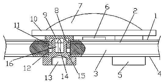
[0019] see figure 1 , the embodiment of the present invention includes:

[0020] An LED light bar with lamp pins plugged in, comprising: a connector 5, a strip circuit board, an LED wick 6 and a lampshade, the LED wicks 6 are arranged on the strip circuit board at intervals, and the strip circuit board includes The surface ink layer 1, the conductive circuit layer 2 and the glass fiber board layer 3, the conductive circuit layer 2 is arranged between the surface ink layer 1 and the glass fiber board layer 3, and the...


PUM


Abstract

The invention discloses a pin-inserted LED lamp strip. The pin-inserted LED lamp strip comprises insertion pieces, a strip circuit board, an LED lamp wick and a lamp cover; the lamp cover comprises anarc shell and a ring; the strip circuit board is provided with positioning holes positioned under the erring; multiple lamp pins inserted in the positioning holes are arranged at the bottom of the ring; the insertion pieces are arranged under the strip circuit board, and positioning columns inserted in the positioning holes are arranged at the top; blind holes are inwards recessed in the bottomsof the lamp pins; embedding holes are concentrically formed in the tops of the blind holes; the positioning columns are provided with multiple elastic rods extending into the blind holes and bonded with the inner walls of the blind holes; limiting blocks positioned in the embedding holes are arranged at the top ends of the elastic rods; and the ring is provided with thread holes extending into thepositioning columns. Through the mode, the pin-inserted LED lamp strip realizes connection between the insertion pieces and the lamp pins, needs no glue, and is excellent in environmental protection,stable in structure and convenient to fix the LED lamp strips on a support frame.

Description

technical field [0001] The invention relates to the technical field of LED light bars, in particular to an LED light bar with lamp pins plugged in. Background technique [0002] In recent years, LED technology has developed rapidly in the field of lighting. LED light strips are light and thin, have good energy-saving properties, high luminous efficiency, and long service life, so they have been vigorously developed in recent years. In addition, due to the fast response and low heat generation of LED light bars, they are widely used in the backlight field of liquid crystal displays, which promotes the development of displays. [0003] Multiple LED wicks are usually installed at intervals on the LED light bar. In order to strengthen the protection of the LED wicks and improve the uniformity of light output, it is necessary to drill a lampshade fixing hole on the LED light bar to install the lampshade and fix it with glue, which is not environmentally friendly. In addition, in...

Claims


Application Information

Patent Timeline
Patent Type & Authority Applications(China)
IPC IPC(8): F21S4/20F21V19/00F21V23/00F21V23/06F21V29/89F21Y115/10
CPCF21S4/20F21V19/0025F21V23/00F21V23/06F21V29/89F21Y2115/10
Inventor 朱道田
Owner 江苏运鸿辉电子科技有限公司
Learn More