Self-rotating spraying device and washing machine

A spray device and self-rotating technology, applied in the field of washing machines, can solve the problems of unsatisfactory spray effect, weakened spray direction, weak spray water flow, etc., to achieve wide spray coverage, improve spray efficiency and effect, low cost effect

Active Publication Date: 2018-11-13
QINGDAO HAIER WASHING ELECTRIC APPLIANCES CO LTD +1
View PDF12 Cites 0 Cited by
  • Summary
  • Abstract
  • Description
  • Claims
  • Application Information

AI Technical Summary

Problems solved by technology

Although this spray device can make the water flowing out of the water outlet form a 360° omni-directional rotating spray, and the spray coverage area is large, but the large spray area will also cause the problem of weak spray water flow
In the actual operation of the washing machine, the spraying range can be appropriately increased on the basis of the original spraying direction, but the aforementioned patent greatly weakens the original spraying direction, and the spraying effect is relatively unsatisfactory

Method used


Image

  • Self-rotating spraying device and washing machine
  • Self-rotating spraying device and washing machine
  • Self-rotating spraying device and washing machine

Examples


Embodiment 1

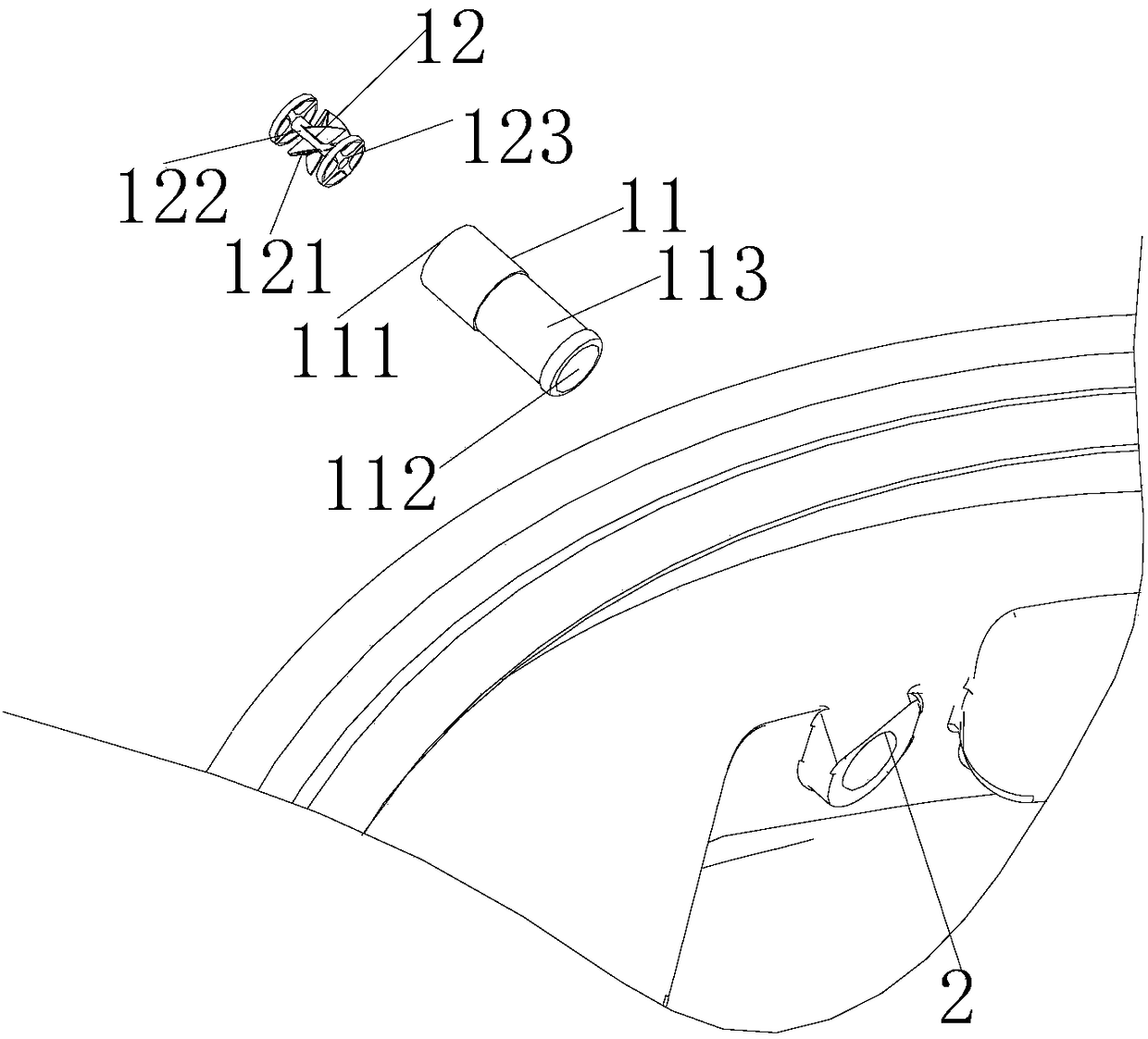
[0061] Such as Figure 1-7 As shown, in this embodiment, the self-rotating spray device 1 is arranged on the drum washing machine. In this embodiment, it is installed on the sealing window gasket 3 of the drum washing machine, and the sealing window gasket 3 has an air inlet 4. It is convenient for the air supply of the drying system. Of course, there is no such structure on the sealing window gasket 3 of the non-drying type drum washing machine. At least one installation hole 2 is provided on the sealing window gasket 3 , and the self-rotating spray device 1 is detachably arranged in the installation hole 2 .

[0062] The self-rotating shower device 1 includes

[0063] Spray head 11, in which a through hole for water flow is set, one end of the through hole is a water inlet 111, and the other end is a water outlet 112, and the water inlet 111 is connected to a water inlet pipeline;

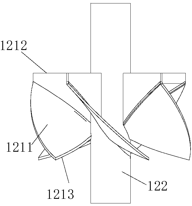
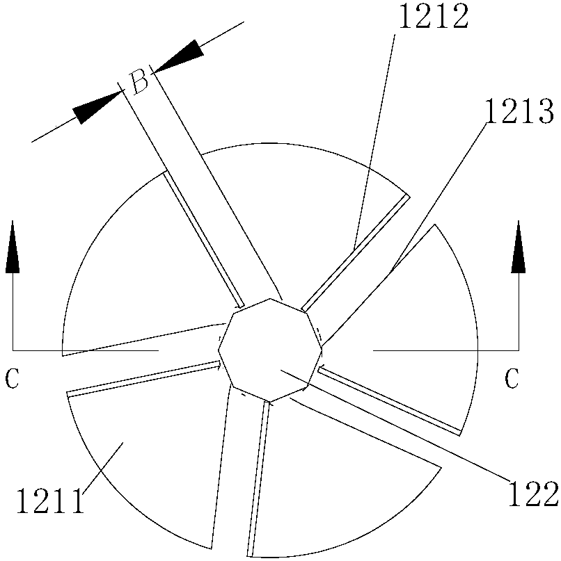
[0064] The self-rotating assembly 12, the self-rotating assembly 12 is arranged in the thro...

Embodiment 2

[0075] Such as Figure 1-Figure 7 As shown, in this embodiment, the self-rotating spray device 1 is arranged on the drum washing machine. In this embodiment, it is installed on the sealing window gasket 3 of the drum washing machine, and the sealing window gasket 3 has an air inlet 4. It is convenient for the air supply of the drying system. Of course, the sealing window gasket 3 of the non-drying type drum washing machine does not have this structure. At least one installation hole 2 is provided on the sealing window gasket 3 , and the self-rotating spray device 1 is detachably arranged in the installation hole 2 .

[0076] The self-rotating shower device 1 includes

[0077] Spray head 11, in which a through hole for water flow is set, one end of the through hole is a water inlet 111, and the other end is a water outlet 112, and the water inlet 111 is connected to a water inlet pipeline;

[0078]The self-rotating assembly 12, the self-rotating assembly 12 is arranged in the...


PUM


Abstract

The invention discloses a self-rotating spraying device and a washing machine. The self-rotating spraying device comprises a spraying head and a self-rotating assembly; a through hole through which water flow passes is formed in the spraying head, a water inlet is formed in one end of the through hole and connected with a water inlet pipe, and a water outlet is formed in the other end of the through hole; the self-rotating assembly is disposed on the portion, at the water outlet, of the interior of the through hole in the spraying head and comprises a bearing base, a rotating shaft and an impeller arranged on the rotating shaft; the sprayed water flow impacts the impeller to make the impeller rotate, and the spraying and discharging direction of a part of the water flow is changed. According to the self-rotating spraying device, the spraying range is obviously enlarged, and the spraying efficiency and effect are improved; moreover, the device has a simple structure, few components andparts, a low cost and high reliability.

Description

technical field [0001] The invention relates to the technical field of washing machines, in particular to a self-rotating spray device for washing machines and a washing machine with the same. Background technique [0002] The existing washing machine's water inlet spraying device, door and window spraying device and water circulation spraying device have a small spraying range of the spraying head and poor spraying effect. [0003] Generally, in order to enhance the spraying effect, people enlarge the spraying device or install multiple spraying devices. But in doing so, the space taken by the spraying device is increased, thereby increasing the volume of the washing machine, and simultaneously increasing the consumption of water and energy. [0004] The Chinese patent with the application number 201610514730.2 discloses a spraying device for a washing machine and a washing machine having the same. The spraying device includes: a water inlet pipe and a shower head assembly...

Claims


Application Information

Patent Timeline
Patent Type & Authority Applications(China)
IPC IPC(8): D06F17/04B05B3/06
CPCB05B3/06D06F17/04
Inventor 赵志强许升李洋
Owner QINGDAO HAIER WASHING ELECTRIC APPLIANCES CO LTD
Why Eureka
Try Eureka