
A wing tilt control mechanism and aircraft

A control mechanism and aircraft technology, applied in the field of unmanned aerial vehicles, can solve the problems affecting the flying quality of unmanned aerial vehicles, and achieve the effect of ensuring the flying quality

Active Publication Date: 2020-08-25
GOERTEK ROBTICS CO LTD
View PDF8 Cites 0 Cited by
  • Summary
  • Abstract
  • Description
  • Claims
  • Application Information

AI Technical Summary

Problems solved by technology

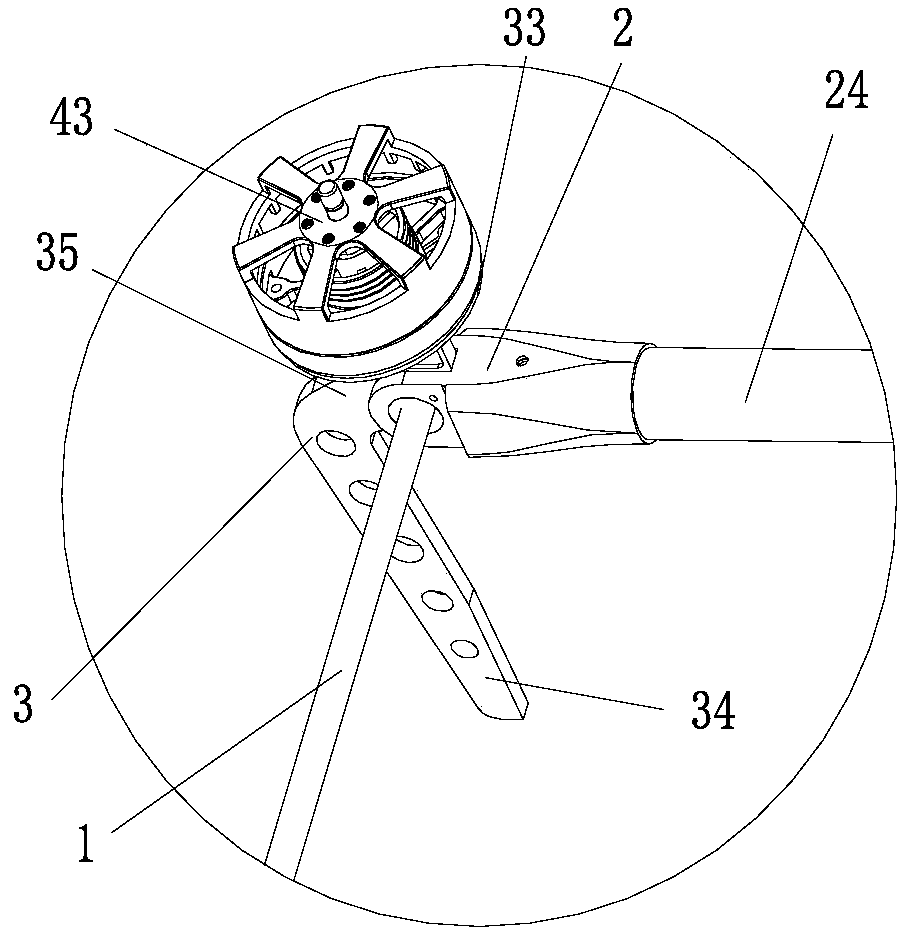
However, in the prior art, there is a certain gap when the drive equipment or / and the drive transmission mechanism, such as the steering gear or the speed reducer that controls the rotation of the wing, cooperate with the transmission gear and other parts, so there is a gap between the wing and the tilting power. At a certain angle, the entire tilting mechanism can still rotate in the vacant position caused by this gap, which affects the flight quality of the drone

Method used


Image

  • A wing tilt control mechanism and aircraft
  • A wing tilt control mechanism and aircraft
  • A wing tilt control mechanism and aircraft

Examples


Embodiment Construction

[0034] Various exemplary embodiments of the present invention will now be described in detail with reference to the accompanying drawings. It should be noted that unless specifically stated otherwise, the relative arrangement, numerical expressions and numerical values ​​of the components and steps set forth in these embodiments do not limit the scope of the present invention.

[0035] The following description of at least one exemplary embodiment is actually only illustrative, and in no way serves as any limitation to the present invention and its application or use.

[0036] The technologies, methods, and equipment known to those of ordinary skill in the relevant fields may not be discussed in detail, but where appropriate, the technologies, methods, and equipment should be regarded as part of the specification.

[0037] In all the examples shown and discussed herein, any specific value should be interpreted as merely exemplary and not as limiting. Therefore, other examples of the...


PUM


Abstract

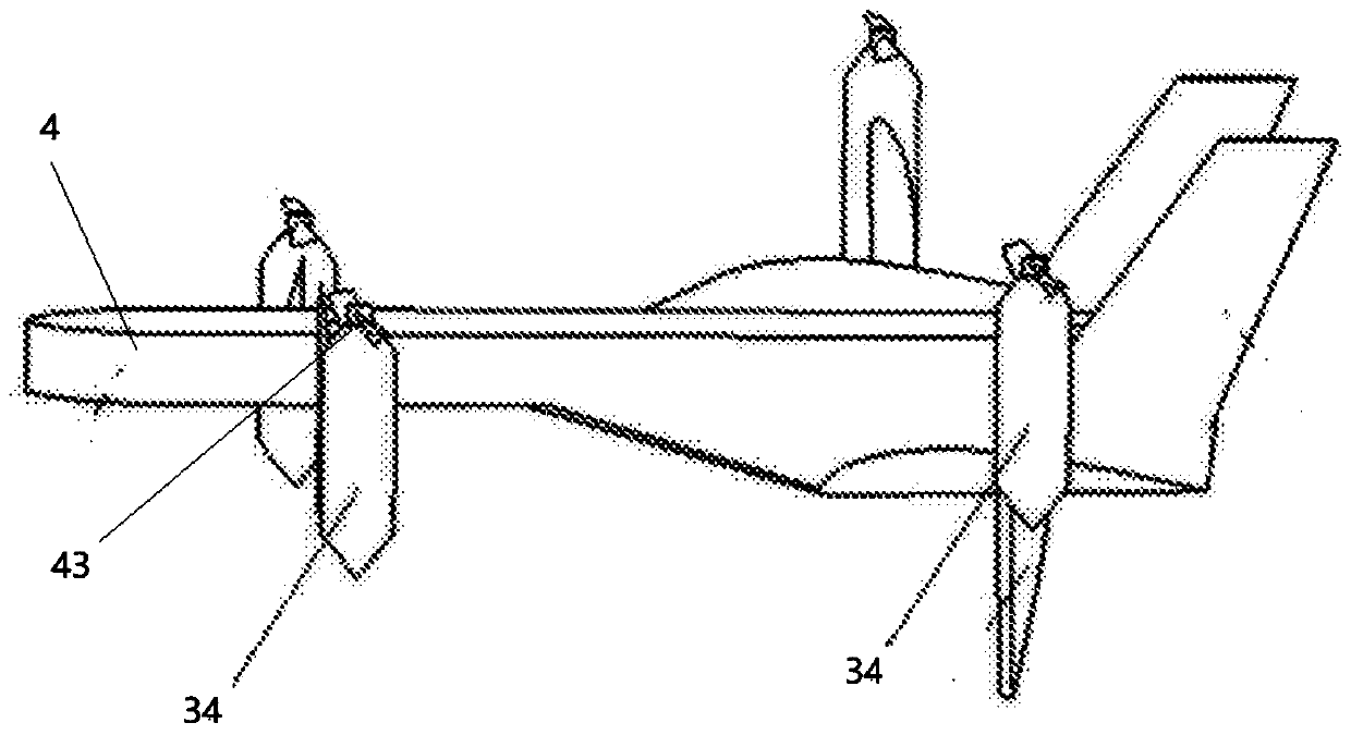
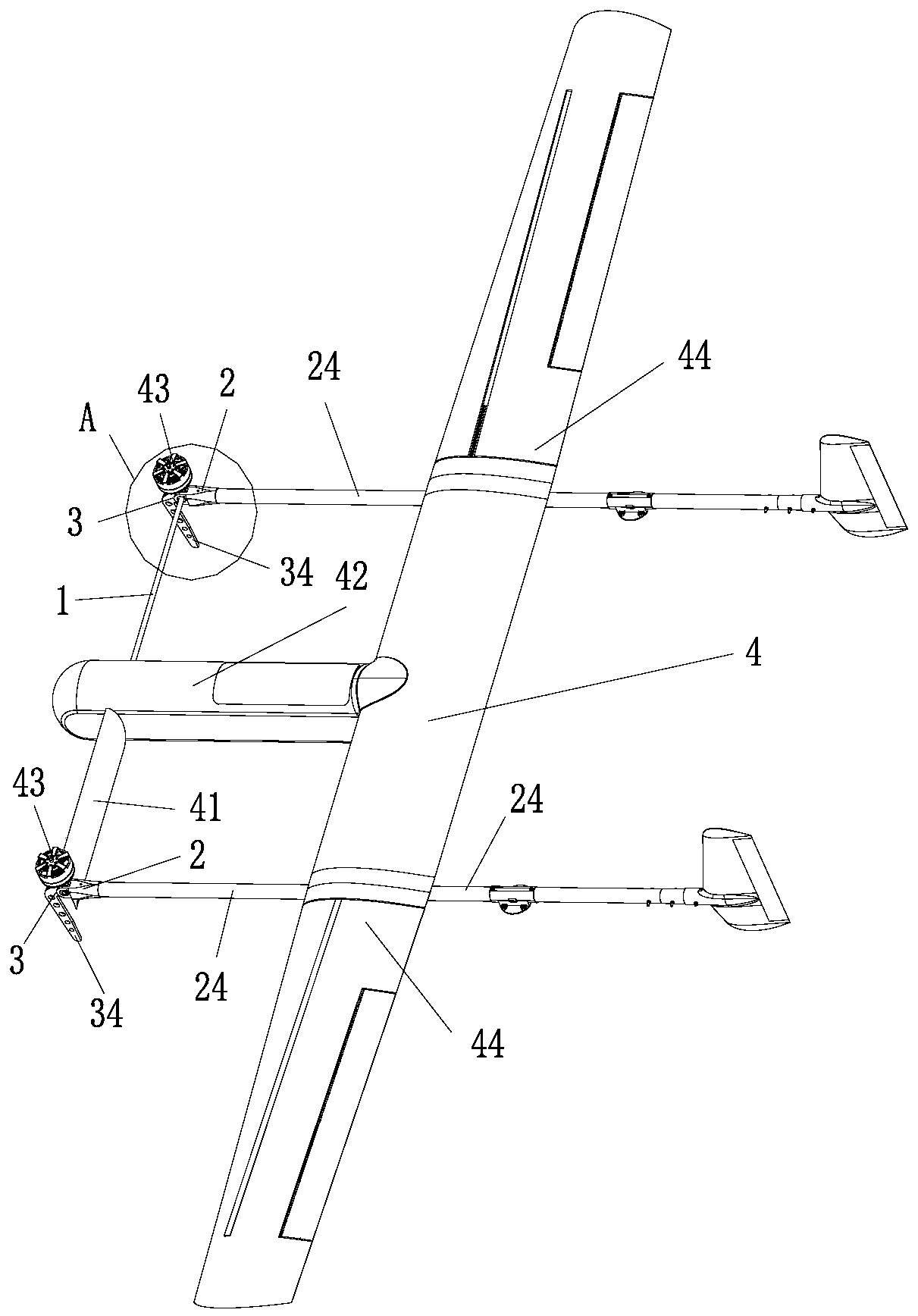
The invention discloses a wing tilting rotating control mechanism and an aircraft. The wing tilting rotating control mechanism includes rotating shafts, rotating shaft brackets and limiting members. The rotating shafts are used for being fixedly connected with wings and driving the wings to rotate. The rotating shaft brackets are used for being fixedly disposed on the aircraft and being rotatablyconnected with the rotating shafts, and limiting portions are arranged at the positions at which the rotating shaft brackets are rotatably connected with the rotating shafts. The limiting members arefixedly connected with the rotating shafts, and the limiting members are provided with first limiting surfaces and second limiting surfaces which correspond to the limiting portions. The first limiting surfaces or the second limiting surfaces can separately abut against the limiting portions following the rotation of the rotating shafts, and rotating force is continuously applied on the rotating shafts to enable the first limiting surfaces or the second limiting surfaces to continuously abut against the limiting portions. The wing tilting rotating control mechanism has the technical effect that the positions of the wings relative to a fuselage can be stably limited, no limiting phantom is achieved, and the flight quality of the aircraft is ensured.

Description

Technical field [0001] The present invention relates to the technical field of unmanned aerial vehicles, and more specifically, to a wing tilt control mechanism and an aircraft. Background technique [0002] UAV is the abbreviation for unmanned aircraft, which is an unmanned aircraft operated by radio remote control equipment and self-provided program control device, or it is completely or intermittently operated by onboard computer autonomously. Because of its low cost, high efficiency, no risk of casualties, strong survivability, good maneuverability, and convenient use, it is currently widely used in various industries, such as military, film and television industries. [0003] In the aerospace field, the front wing of the UAV can place the horizontal stable surface in front of the main wing. It can generate vortex above the main wing and increase the stall angle of attack. The movable front wing is not only used to generate eddy currents, but also used to improve the stabilit...

Claims


Application Information

Patent Timeline
Patent Type & Authority Patents(China)
IPC IPC(8): B64C3/38
CPCB64C3/38
Inventor 侯铭硕韩伟石翔颜安
Owner GOERTEK ROBTICS CO LTD
Learn More