Connecting wire positioning clip suitable for high voltage
What is Al technical title?
Al technical title is built by PatSnap Al team. It summarizes the technical point description of the patent document.
A positioning clip and wire technology, applied in the direction of connection, connection insulation, conductive connection, etc., can solve the problem of poor clamping effect of the positioning clip, and achieve the effect of enhancing the clamping effect, prolonging the service life and reducing economic losses.
Active Publication Date: 2018-11-06
GULIFA ELECTRIC +1
View PDF4 Cites 1 Cited by
Summary
Abstract
Description
Claims
Application Information
AI Technical Summary
This helps you quickly interpret patents by identifying the three key elements:
Problems solved by technology
Method used
Benefits of technology
Problems solved by technology
[0004] The purpose of the present invention is to provide a positioning clamp for continuous wires suitable for high voltage, which has the advantage of good clamping effect and solves the problem of poor clamping effect of existing positioning clamps
Method used
Image
Click on the blue label to locate the original text in one second.
Reading with bidirectional positioning of images and text.
Examples
Embodiment Construction
[0016] The following will clearly and completely describe the technical solutions in the embodiments of the present invention with reference to the accompanying drawings in the embodiments of the present invention. Obviously, the described embodiments are only some, not all, embodiments of the present invention. Based on the embodiments of the present invention, all other embodiments obtained by persons of ordinary skill in the art without making creative efforts belong to the protection scope of the present invention.
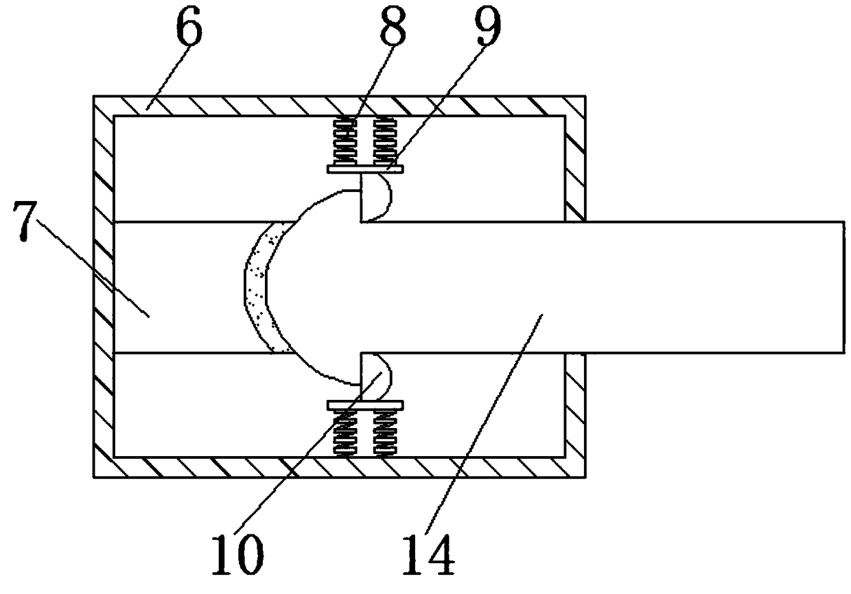
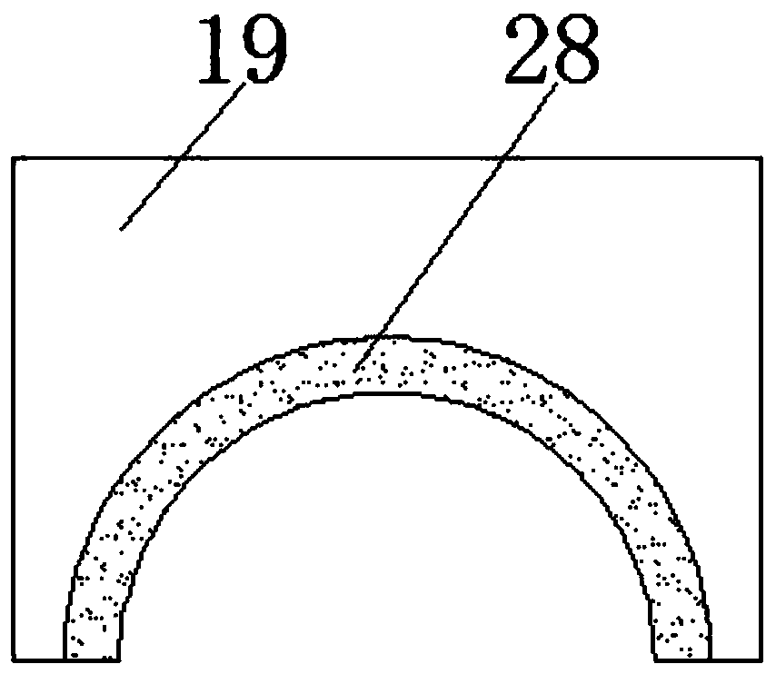
[0017] see Figure 1-3 , a positioning clip suitable for high-voltage splicing wires, including an insulating shell 1, an insulating layer 29 is arranged on the outside of the insulating shell 1, through the insulating layer 29, it is convenient for users to carry out wire connection work under high-voltage conditions, and the inner cavity of the insulating shell 1 The left side of the first wire splint 2 is provided with the first wire splint 2, the left side...
PUM
Abstract
The invention discloses a connecting wire positioning clip suitable for high voltage, comprising an insulating casing, wherein a first wire clamp plate is disposed on the left side of the inner cavityof the insulating casing, a first wire guiding cylinder is connected to the left side of the first wire clamp plate, the inner cavity of the first wire guiding cylinder is provided with a first wire,and the right side of the first wire clamp plate is connected with a dovetail shaped bump. Due to the matching of the first wire clamp plate, the first wire guiding cylinder, the first wire, the dovetail shaped bump, the fixing block, the limiting block, the first snap spring, the fixing plate, the semi-arc snap block, the second wire clamp plate, the dovetail shaped groove, the second wire guiding cylinder, the snapping rod, the supporting seat, the cross bar, the blocking bar, the second snap spring, and the fixture block, the invention may fully clamp the first wire and the second wire toenhance the clamping effect of the positioning clip, which solves the problem that the clamping function of the existing positioning clip is poor, avoids the phenomenon that the wire is separated fromthe inside of the positioning clip, and is worthy of popularization.
Description
technical field [0001] The invention relates to the technical field of wire positioning clamps, in particular to a positioning clamp for continuous wires suitable for high voltage. Background technique [0002] Conductor refers to the material used for wire and cable. In industry, it also refers to wire. It is generally made of copper or aluminum, and it is also made of silver wire (good electrical conductivity and thermal performance) to conduct current or conduct heat. [0003] In the existing electrical equipment, the internal parts of the electrical equipment are connected with the wires of the host, and the wire ends need to be placed on the positioning clips. However, the existing positioning clips have poor clamping effect. Users use the positioning clips for a long time, and the positioning clips are easy to fall off or loosen. , It is easy to cause the wire to break away from the inside of the positioning clip, causing damage to the electrical equipment, reducing th...
Claims
Application Information
Patent Timeline
Application Date:The date an application was filed.
Publication Date:The date a patent or application was officially published.
First Publication Date:The earliest publication date of a patent with the same application number.
Issue Date:Publication date of the patent grant document.
PCT Entry Date:The Entry date of PCT National Phase.
Estimated Expiry Date:The statutory expiry date of a patent right according to the Patent Law, and it is the longest term of protection that the patent right can achieve without the termination of the patent right due to other reasons(Term extension factor has been taken into account ).
Invalid Date:Actual expiry date is based on effective date or publication date of legal transaction data of invalid patent.