
Siphon effect demonstrating device

A demonstration device, a technology of siphon effect, applied in the field of teaching aids, can solve the problem of not being able to quickly understand the siphon effect, etc., and achieve the effect of improving friction

Inactive Publication Date: 2018-11-06
张桉煜
View PDF0 Cites 2 Cited by
  • Summary
  • Abstract
  • Description
  • Claims
  • Application Information

AI Technical Summary

Problems solved by technology

[0005] Aiming at the deficiencies of the prior art, the present invention provides a siphon effect demonstration device, which solves the problem of not being able to quickly understand the siphon effect

Method used


Image

  • Siphon effect demonstrating device
  • Siphon effect demonstrating device
  • Siphon effect demonstrating device

Examples


Embodiment Construction

[0028] The following will clearly and completely describe the technical solutions in the embodiments of the present invention with reference to the accompanying drawings in the embodiments of the present invention. Obviously, the described embodiments are only some, not all, embodiments of the present invention. Based on the embodiments of the present invention, all other embodiments obtained by persons of ordinary skill in the art without making creative efforts belong to the protection scope of the present invention.

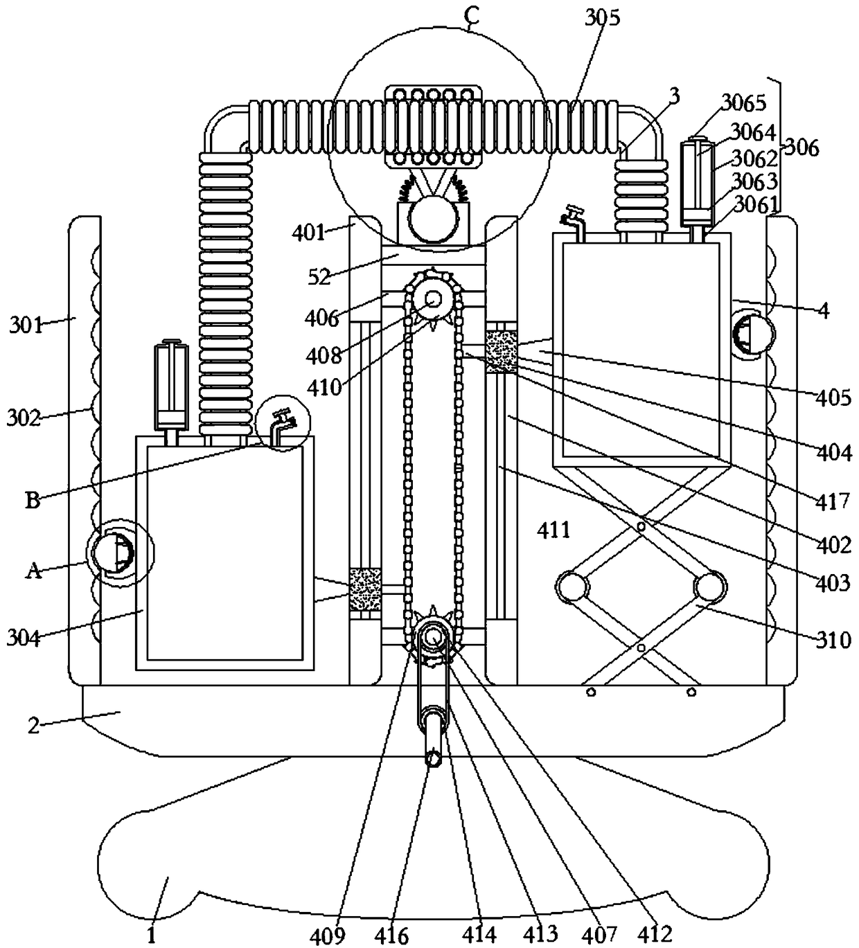
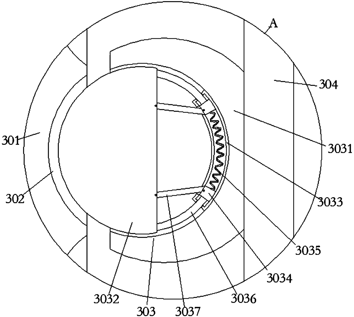
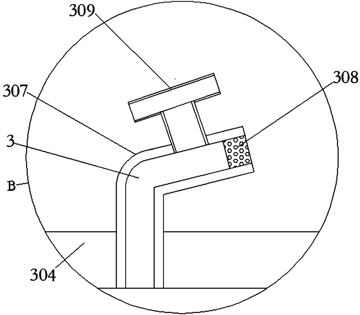
[0029] see Figure 1-5 , the present invention provides a technical solution: a siphon effect demonstration device, including a base 1, the top of the base 1 is fixedly connected with a carrier plate 2, the upper surface of the carrier plate 2 is fixedly connected with a siphon demonstrator 3, and the siphon demonstrator 3 A linkage mechanism 4 is arranged between them, and a stabilizer 5 is sleeved on the siphon demonstrator 3 .

[0030]The siphon demonstrat...


PUM


Abstract

The present invention relates to the field of teaching aids and in particular to a siphon effect demonstrating device. The technical problem to be solved by the present invention is that high school students cannot quickly understand the siphon effect. In order to solve the above technical problem, the present invention provides a siphon effect demonstrating device comprising a base. The top of the base is fixedly connected with a carrier plate. The top surface of the carrier plate is fixedly connected with siphon demonstrators. A linkage mechanism is arranged between the siphon demonstrators.The siphon demonstrators are sleeved with stabilizers. In the present invention, when a rotating chain rotates, two liquid tanks can be simultaneously moved in opposite directions. At this time, a height difference between the two liquid tanks can be changed so that the flow of the liquid inside the two liquid tanks can be clearly understood after the height difference is changed. After the pressure intensity in the liquid tanks changes, the students can clearly see the flow direction and the flow velocity of the liquid in the two liquid tanks.

Description

technical field [0001] The invention relates to the technical field of teaching aids, in particular to a siphon effect demonstration device. Background technique [0002] The siphon effect, also known as the siphon phenomenon, physically means that due to the gravitational force and potential energy difference between liquid molecules, the liquid will flow from the side with high pressure to the side with low pressure. Because the water surface of the nozzle is subjected to different atmospheric pressures, the water will flow from the side with high pressure to the side with low pressure until the atmospheric pressure on both sides is equal, the water surface in the container becomes the same height, and the water will stop flowing. The water in the container can be drawn out quickly by using the siphon phenomenon. [0003] However, in physics classrooms, teachers generally explain the principle of this phenomenon through textbooks, but do not show it to students through pr...

Claims


Application Information

Patent Timeline
Patent Type & Authority Applications(China)
IPC IPC(8): G09B23/12
CPCG09B23/12
Inventor 张桉煜
Owner 张桉煜
Learn More