Vehicle identification device, roadside unit and method for etc system
A vehicle identification and vehicle technology, applied in the field of intelligent transportation, can solve the problem of inaccurate identification of vehicle models, and achieve the effect of preventing vehicle evasion and improving accuracy.
- Summary
- Abstract
- Description
- Claims
- Application Information
AI Technical Summary
Problems solved by technology
Method used
Image

Examples
Embodiment 1
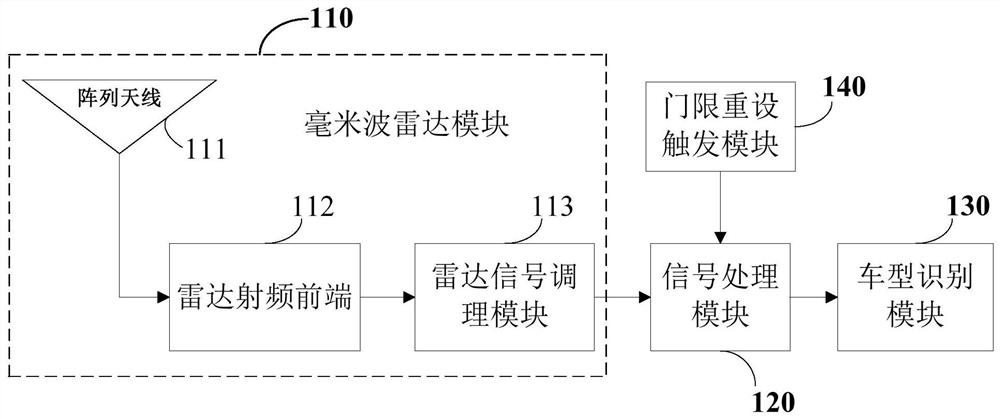
[0044] Please refer to figure 1, is a functional structural block diagram of a vehicle identification device for an ETC system, the vehicle identification device includes a millimeter wave radar module 110, a signal processing module 120, a vehicle type identification module 130, and may also include a threshold reset trigger module 140. Among them, the millimeter wave radar module 110 may include an array antenna 111 and a radar radio frequency front end 112. The array antenna 111 is composed of a plurality of antenna sub-array units in horizontal and vertical directions, and the sub-units of the array antenna 111 are arranged in an array. The array antenna 111 receives the millimeter-wave radar echo signal reflected by the target within the radiation range of the millimeter-wave radar signal, and at the same time transmits the millimeter-wave radar signal modulated with continuous wave LFM (Linear Frequency Modulation) through the array antenna 111. The radar RF front-end 1...
Embodiment 2
[0082] like Figure 4 As shown, it is a block diagram of the car model matching function used in the vehicle identification device of the ETC system. The vehicle identification device includes a millimeter-wave radar module 211, a signal processing module 212 and a vehicle type identification module 213, and may also include a wireless communication module 215 and a vehicle type matching module 216. The millimeter-wave radar module 211 is configured to receive and transmit millimeter-wave radar signals, and send the received echo signals to the signal processing module 212; the signal processing module 212 processes the echo signals to obtain characteristic information of the vehicle, and The characteristic information of the vehicle is sent to the vehicle type identification module 213 , and the vehicle type identification module 213 recognizes the vehicle type information according to the obtained vehicle characteristic information and sends it to the vehicle type matching m...
Embodiment 3
[0085] like Figure 5 Shown is a flow chart of a vehicle identification method for the ETC system;
[0086] Its main steps are:
[0087] Receive and transmit millimeter wave radar signals.
[0088] The echo signal of the millimeter wave radar is processed to obtain the characteristic information of the vehicle.
[0089] The vehicle type information is identified according to the obtained characteristic information of the vehicle.
[0090] Specific steps are as follows:
[0091] Step 301, acquire the echo signal of the millimeter-wave radar signal, and perform zero-IF conversion on the echo signal.
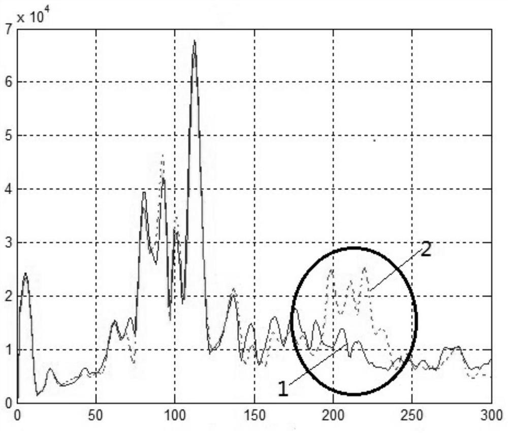
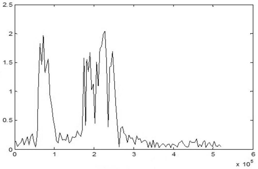
[0092] Step 302, perform time-frequency transformation on the echo signal subjected to zero-IF conversion, so as to generate a histogram of the target amplitude value curve.
[0093] Step 303, comparing the target amplitude value curve with the threshold curve. According to the comparison result, it is determined whether there is a vehicle passing through the radiation range ...
PUM
 Abstract
Description
Claims
Application Information
 - R&D
- Intellectual Property
- Life Sciences
- Materials
- Tech Scout
- Unparalleled Data Quality
- Higher Quality Content
- 60% Fewer Hallucinations
Browse by: Latest US Patents, China's latest patents, Technical Efficacy Thesaurus, Application Domain, Technology Topic, Popular Technical Reports.
© 2025 PatSnap. All rights reserved.Legal|Privacy policy|Modern Slavery Act Transparency Statement|Sitemap|About US| Contact US: help@patsnap.com