Water leakage detection device for diaphragm gas meter movement and leakage detection method

A membrane gas meter and gas meter technology, applied in the direction of detecting the appearance of fluid at the leak point, using liquid/vacuum degree to measure the liquid tightness, etc., can solve the problem that the position of the leak point and the movement cannot be displayed accurately and intuitively Leak detection operation efficiency is not high, to achieve the effect of convenient leak detection operation, improve work efficiency, and accurate detection

Pending Publication Date: 2018-11-06
真兰仪表科技有限公司
View PDF8 Cites 0 Cited by
  • Summary
  • Abstract
  • Description
  • Claims
  • Application Information

AI Technical Summary

Problems solved by technology

[0003] In order to solve the above technical problems, the present invention provides a water-type leak detection device for membrane gas meter cores, which solves the problem that the existing membrane gas meter core leak detection equipment cannot accurately and intuitively display the location of the leak point, which is difficult for maintenance. The movement brings certain difficult problems, and further solves the problem that the efficiency of the movement leak detection operation is not high. The leakage operation is convenient, and it can visually display the position of the leak point of the chamber in the movement, and each chamber in the movement can be detected at one time, which can improve the detection efficiency

Method used


Image

  • Water leakage detection device for diaphragm gas meter movement and leakage detection method
  • Water leakage detection device for diaphragm gas meter movement and leakage detection method
  • Water leakage detection device for diaphragm gas meter movement and leakage detection method

Examples


Embodiment Construction

[0027] The specific implementation manner of the present invention will be described in further detail below by describing the best embodiment with reference to the accompanying drawings.

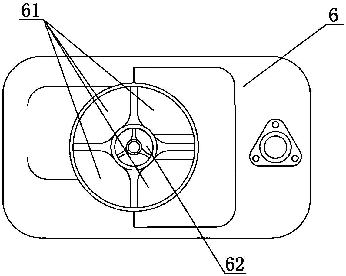
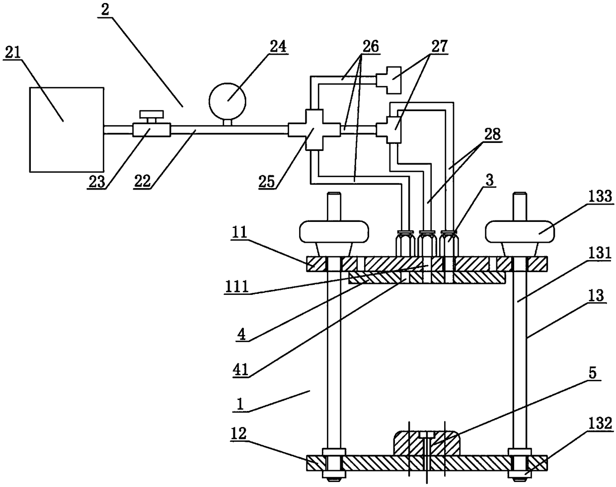
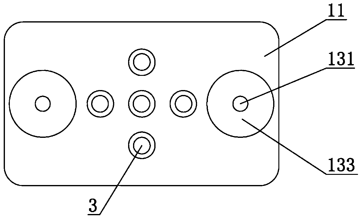
[0028] Concrete embodiment of the present invention is: as figure 2 As shown, a water-type leak detection device for a membrane gas meter movement includes a positioning bracket 1 for positioning and sealing the membrane gas meter movement and a control gas path 2 connected to the positioning bracket 1. The positioning bracket 1 is provided with a Each chamber of the movement communicates with an air pipe joint 3, and the air pipe joint 3 is connected with the control air circuit 2. After the leak detection device positions and seals the movement of the diaphragm gas meter through the positioning bracket 1, the positioning bracket 1 is placed in a transparent container filled with clear water, and the air is passed into each chamber of the movement through the control air circuit 2. High-...


PUM


Abstract

The invention discloses a water leakage detection device for a diaphragm gas meter movement and a leakage detection method and belongs to the technical field of leakage detection of diaphragm gas meter movements. The water leakage detection device for the diaphragm gas meter movement comprises a positioning bracket and a control gas path, wherein the positioning bracket is used for positioning andsealing the diaphragm gas meter movement; the control gas path is connected onto the positioning bracket; a gas pipe joint communicated with each cavity of the movement is arranged on the positioningbracket; the gas pipe joint is connected with the control gas path. The leakage detection method comprises the following steps: positioning and sealing the diaphragm gas meter movement, putting a leakage detection device provided with the movement into clean water, introducing high-pressure gases into the movement, and observing the phenomenon in the clean water for judgment. The water leakage detection device for the diaphragm gas meter movement and the leakage detection method disclosed by the invention have the beneficial effects that the leakage detection device is simple in overall structure, the movement is convenient to position and place, the water leakage detection operation completed by the device is convenient, and the position of a leakage point in the cavity of the movement can be intuitively displayed. Moreover, each cavity in the movement can be detected, and the detection efficiency is improved.

Description

technical field [0001] The invention relates to the technical field of leakage detection of membrane gas meter cores, in particular to a water-type leak detection device and leak detection method for membrane gas meter cores. Background technique [0002] As a metering instrument for measuring gas consumption, gas meters are closely related to people's lives. Such as figure 1 As shown, the commonly used gas meter movement 6 is divided into four capacity chambers 61 and an outlet chamber 62 communicating with the outlet pipe by a partition and a diaphragm. After the valve seat is installed, the sealing of these five chambers sex to meet the requirements. At present, the membrane gas meter industry is prevalent at home and abroad, but when it comes to the sealing of the core, the most commonly used test is to put the core on the leak detection equipment, apply negative pressure to the core, and after the specified pressure, start to balance. Observe the leaks displayed on t...

Claims


Application Information

Patent Timeline
Patent Type & Authority Applications(China)
IPC IPC(8): G01M3/06
CPCG01M3/06
Inventor 杨艳涛李燕
Owner 真兰仪表科技有限公司
Why Eureka
Try Eureka