Portable power divider mounting device

A technology for installing devices and power dividers, which is applied in the direction of supporting machines, mechanical equipment, machine tables/supports, etc., can solve problems such as the inability to install power dividers, and achieve the effects of simple structure, convenient use, and low manufacturing cost

Inactive Publication Date: 2018-11-06
CHENGDU XUSITE TECH CO LTD
View PDF0 Cites 0 Cited by
  • Summary
  • Abstract
  • Description
  • Claims
  • Application Information

AI Technical Summary

Problems solved by technology

[0002] When the existing power splitter is installed, the power splitter is usually installed on the fixed object directly through the screw hole provided on the power splitter shell, which requires the width of the fixed object to be larger than the power splitter shell The distance between the upper screw holes, if the fixed object is a narrow plate or block, and the width of the surface that can be used for installation is smaller than the distance between the screw holes on the power divider shell, the power divider cannot be installed

Method used


Image

  • Portable power divider mounting device
  • Portable power divider mounting device
  • Portable power divider mounting device

Examples


Embodiment 1

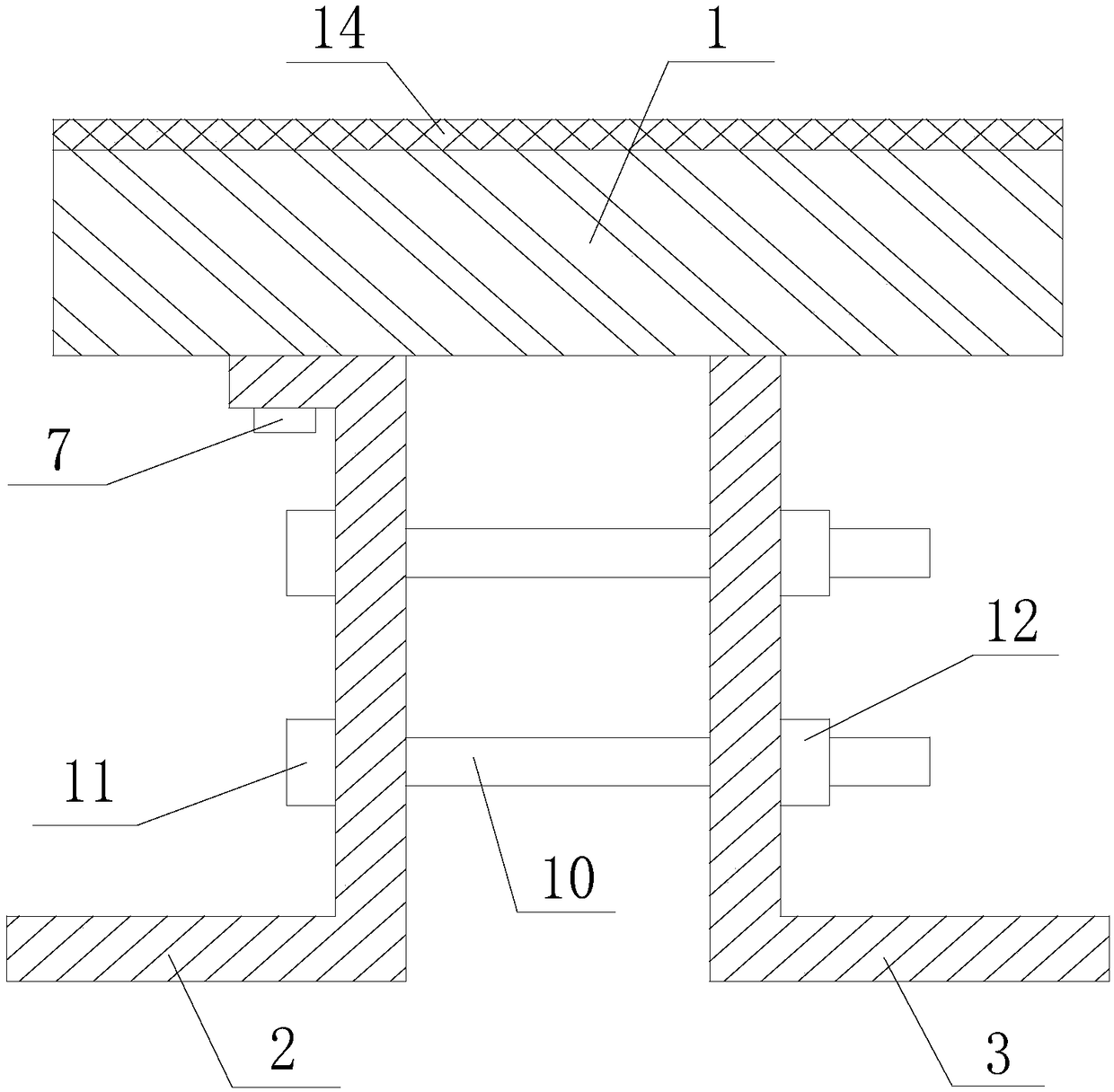
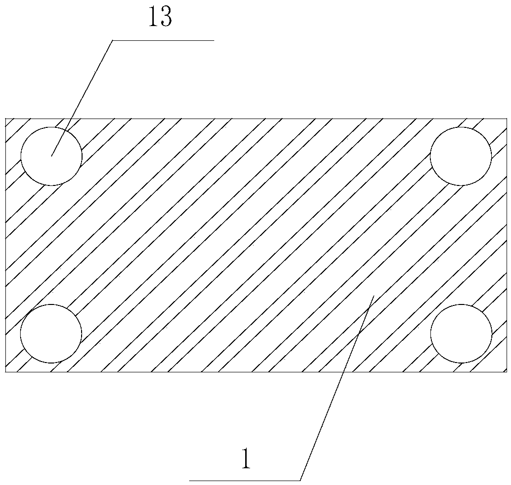
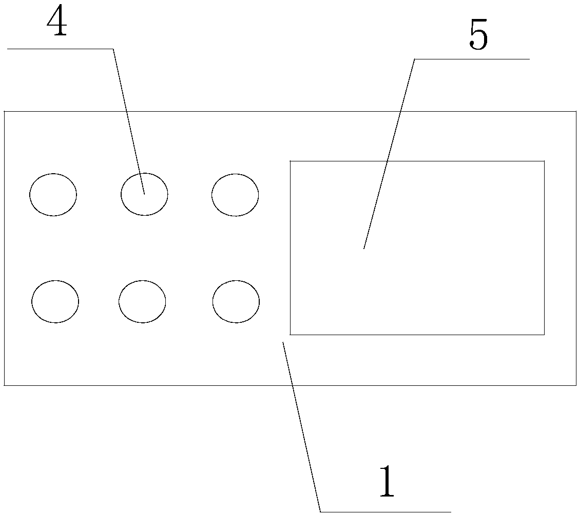
[0024] Such as Figure 1-4 As shown, a portable power splitter installation device includes a fixed table 1, a first mounting plate 2 and a second mounting plate 3, the top of the fixed table 1 is provided with a first blind hole 13, and the bottom of the fixed table 1 One end is provided with a plurality of second blind holes 4, and the other end is provided with sliding grooves 5. The second blind holes 4 are evenly distributed along the length direction of the bottom surface of the fixed table 1. The first blind holes 13 and the second blind holes 4 are equally spaced. An internal thread is provided, and a first through hole 9 is provided on the corresponding positions of the first mounting plate 2 and the second mounting plate 3, and a first boss is integrally connected to the top of the first mounting plate 2, A second through hole 6 is provided in the first boss, and an internal thread is provided in the second through hole 6. The diameter of the second through hole 6 is...

Embodiment 2

[0026] As an optimization to the above-mentioned embodiment, the bottom of the first mounting plate 2 and the second mounting plate 3 are integrally connected with a second boss, and a third through hole 15 is provided in the second boss, when fixing an object Wide, when the first mounting plate 2 and the second mounting plate 3 cannot be installed on the fixed object through the first through hole 9 and the fixing screw 10, the two mounting plates can also be connected through the second boss and the third through hole 12 Installed on the surface of a fixed object; the second blind holes 4 are arranged in pairs in the middle of one end of the bottom of the fixed table 1, and the corresponding second through holes 6 are also provided with two at equal intervals. The second through hole 6 can more firmly fix the first mounting plate 2 on the bottom of the fixed table 1 to prevent it from rotating; A buffer is formed between the tables 1 to prevent collision and friction between...


PUM


Abstract

The invention discloses a portable power divider mounting device. The portable power divider mounting device comprises a fixing table, a first mounting plate and a second mounting plate; first blind holes are formed in the top of the fixing table, a plurality of second blind holes are formed in one end of the bottom of the fixing table, and a sliding groove is formed in the other end of the bottomof the fixing table; first through holes are formed in the corresponding positions of the plate surfaces of the first mounting plate and the second mounting plate, a first convex table is connected to the top of the first mounting plate in an all-in-one mode, second through holes are formed in the first convex table, the diameter of the second through holes is the same as the diameter of the second blind holes, and limiting screws are arranged in the second through holes and the second blind holes in a screwed mode so that the first mounting plate is fixed at the bottom of the fixing table; and a sliding block is connected to the top of the second mounting plate in an all-in-one mode, the sliding block is located in the sliding groove, the first mounting plate is opposite to the second mounting plate, and fixing screws are connected between the corresponding first through holes in the first mounting plate and the second mounting plate. When the portable power divider mounting device is applied, a power divider can be conveniently mounted on a narrower object.

Description

technical field [0001] The invention relates to an auxiliary supporting device for a power divider, in particular to a convenient installation device for a power divider. Background technique [0002] When the existing power splitter is installed, the power splitter is usually installed on the fixed object directly through the screw hole provided on the power splitter shell, which requires the width of the fixed object to be larger than the power splitter shell The distance between the upper screw holes, if the fixed object is a narrow plate or block, and the width of the surface that can be used for installation is smaller than the distance between the screw holes on the power divider shell, the power divider cannot be installed . Contents of the invention [0003] Aiming at the shortcomings of the prior art, the present invention provides a portable power divider installation device, which can conveniently install the power divider on a narrow object during application....

Claims


Application Information

Patent Timeline
Patent Type & Authority Applications(China)
IPC IPC(8): F16M13/02F16M11/04
CPCF16M13/02F16M11/04
Inventor 王东罗志刚江文彬
Owner CHENGDU XUSITE TECH CO LTD
Why Eureka
Try Eureka