Submerged electrochemical in-situ nutrient enrichment device and method for removing nutrient salt from surface water

An in-situ enrichment and nutrient salt technology, applied in the field of water treatment, can solve the problems of low nutrient salt concentration and poor nutrient salt effect, and achieve high-efficiency treatment, convenient operation, and cost reduction

Active Publication Date: 2021-10-08
HARBIN INST OF TECH
View PDF6 Cites 0 Cited by
  • Summary
  • Abstract
  • Description
  • Claims
  • Application Information

AI Technical Summary

Problems solved by technology

[0006] The purpose of the present invention is to solve the problem of poor effect of chemical and biological treatment of nutrient salts due to the low concentration of nutrient salts in surface water, and propose a submerged electrochemical in-situ enrichment device for nutrient salts and a device for removing nutrient salts in surface water method

Method used


Image

  • Submerged electrochemical in-situ nutrient enrichment device and method for removing nutrient salt from surface water
  • Submerged electrochemical in-situ nutrient enrichment device and method for removing nutrient salt from surface water
  • Submerged electrochemical in-situ nutrient enrichment device and method for removing nutrient salt from surface water

Examples


specific Embodiment approach 1

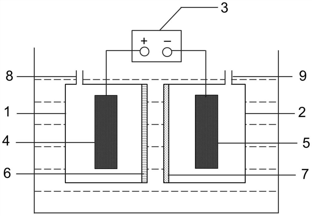
[0037] Specific implementation mode one: combine figure 1 Describe this embodiment, the immersion type electrochemical in-situ enrichment nutrient salt device of this embodiment is made up of anode chamber 1, cathode chamber 2, power supply 3, anode 4, cathode 5, anion exchange membrane 6 and cation exchange membrane 7; 1 is filled with anolyte, and the cathode chamber 2 is filled with catholyte;

[0038] The top of the anode chamber 1 is at least provided with an anode chamber inlet and outlet pipe 8, one of the side walls of the anode chamber 1 is an opening, and the opening of the anode chamber 1 is covered with an anion exchange membrane 6; the top of the cathode chamber 2 is at least provided with a cathode Chamber inlet and outlet water pipes 9, one of the side walls of the cathode chamber 2 is an opening, and the opening of the cathode chamber 2 is covered with a cation exchange membrane 7;

[0039] The anion exchange membrane 6 is arranged opposite to the cation excha...

specific Embodiment approach 2

[0044] Embodiment 2: This embodiment differs from Embodiment 1 in that: the nozzles of the anode chamber inlet and outlet pipes 8 and the cathode chamber inlet and outlet pipes 9 are respectively provided with rubber plugs. Other steps and parameters are the same as those in the first embodiment.

specific Embodiment approach 3

[0045] Embodiment 3: The difference between this embodiment and Embodiment 1 or 2 is that the anion exchange membrane 6 and the opening of the anode chamber 1 are sealed by a sealing ring. Other steps and parameters are the same as those in Embodiment 1 or 2.


PUM


Abstract

A submerged electrochemical in-situ nutrient enrichment device and a method for removing nutrient salt in surface water relate to a nutrient salt enrichment device and method. The purpose is to solve the problem of poor effect of chemical and biological methods on nutrient treatment. The device consists of an anode chamber, a cathode chamber, a power supply, an anode, a cathode, an anion exchange membrane and a cation exchange membrane; one side wall of the anode chamber and the cathode chamber is an open opening and is covered with an anion exchange membrane and a cation exchange membrane respectively; the anion exchange membrane and The cation exchange membranes are arranged opposite. Submerge the anode chamber and cathode chamber in nutrient salt-contaminated water to apply voltage, collect the concentrated phosphate and ammonium salt solutions obtained in the anode chamber and cathode chamber, add magnesium chloride after mixing and adjust the pH to generate struvite, and realize the final elimination of nutrient salt. remove. The device of the invention can in-situ enrich the nutrient salt in the polluted water body, the removal rate of ammonia nitrogen can reach more than 90%, and the removal rate of phosphorus can reach more than 89%. The invention is suitable for removing nutrient salts in surface water.

Description

technical field [0001] The invention belongs to the technical field of water treatment, and in particular relates to an in-situ enrichment device for nutrient salts and a method for removing nutrient salts in surface water. Background technique [0002] Since the reform and opening up, my country's industrial progress has driven economic prosperity and improved the quality of life. However, due to weak environmental awareness and relatively backward treatment facilities for domestic sewage and industrial wastewater, many surface water bodies have been polluted to varying degrees. At present, the research on treatment technology for sewage and wastewater is relatively extensive, but the treatment of polluted surface water bodies is also urgent. In addition to organic pollutants, nutrient pollution also threatens the sustainable development of the economy and society. At present, most of the large and important rivers and lakes in my country, as well as small and medium-sized...

Claims


Application Information

Patent Timeline
Patent Type & Authority Patents(China)
IPC IPC(8): C02F1/469
CPCC02F1/4693
Inventor 冯玉杰蒋晴刘佳宋向茹
Owner HARBIN INST OF TECH
Why Eureka
Try Eureka