Ring wing unmanned aerial vehicle

A technology of unmanned aerial vehicles and ring wings, which is applied in the field of unmanned aerial vehicles and can solve problems such as slow flight speed, poor wind resistance, and short flight time

Active Publication Date: 2018-11-06
XIAN AERONAUTICAL UNIV
View PDF14 Cites 2 Cited by
  • Summary
  • Abstract
  • Description
  • Claims
  • Application Information

AI Technical Summary

Problems solved by technology

However, the shortcomings of the rotor UAV are also obvious: short flight time, short flight distance, slow flight speed, and poor wind resistance

Method used


Image

  • Ring wing unmanned aerial vehicle
  • Ring wing unmanned aerial vehicle
  • Ring wing unmanned aerial vehicle

Examples


Embodiment Construction

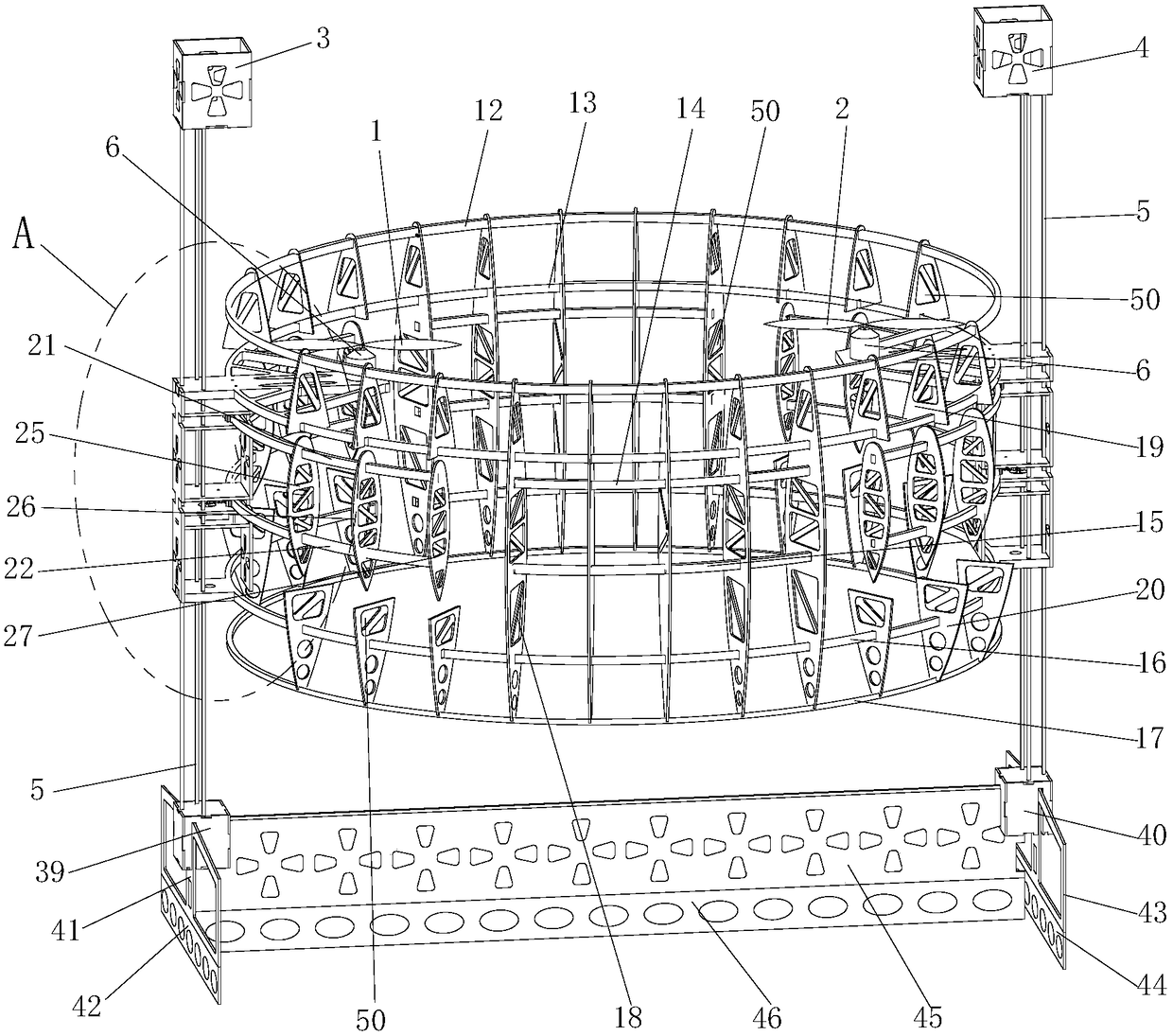
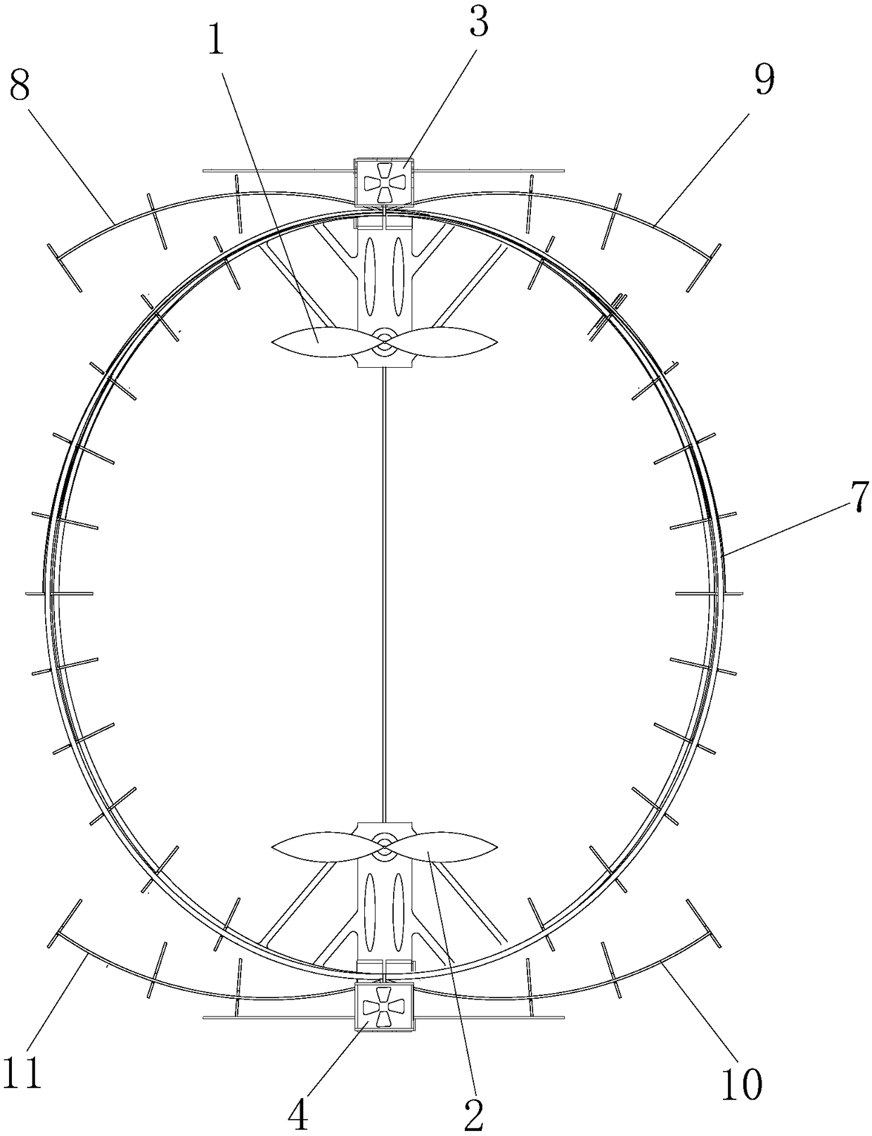
[0055] Such as figure 1 Shown, the present invention comprises annular wing, empennage, left mission warehouse 3, right mission warehouse 4, left fuselage connecting device, right fuselage connecting device, left propeller 1, right propeller 2 and power plant, described left The task warehouse 3 and the right mission warehouse 4 are arranged symmetrically on the left and right sides above the annular wing, and the power unit includes a left power unit and a right power unit, and the left power unit and the right power unit are symmetrically arranged on the inside of the annular wing. On the left and right sides, the left propeller 1 is fixedly installed on the output shaft of the left power unit, the right propeller 2 is fixedly installed on the output shaft of the right power unit, and the left power unit is fixedly installed on the left fuselage connection On the device, the right power unit is fixedly installed on the right fuselage connection device, the left fuselage conn...


PUM

PropertyMeasurementUnit
Angleaaaaaaaaaa

Abstract

The invention discloses a ring wing unmanned aerial vehicle, comprising a ring wing, a tail wing, a left task compartment, a right task compartment, a left fuselage connecting device, a right fuselageconnecting device, a left propeller, a right propeller and a power device. The power device comprises a left power device and a right power device. The left fuselage connecting device and the right fuselage connecting device are identical in structure and each includes a fuselage connecting rod and a fuselage case. According to the invention, the annular wing and double propeller structure is adopted, so that the unmanned aerial vehicle can realize vertical take-off and landing, the ring wing unmanned aerial vehicle has the characteristics of long flight time, long flight distance, high flight speed, strong wind resistance and the like, unfolding wings are also arranged on the ring wing of the unmanned aerial vehicle, so that the ring wing has high operability and flexible in turning.

Description

technical field [0001] The invention belongs to the technical field of unmanned aerial vehicles, in particular to a ring-wing unmanned aerial vehicle. Background technique [0002] At present, UAVs on the market can be divided into two categories: fixed-wing UAVs and rotary-wing UAVs. Fixed-wing unmanned aerial vehicles generate lift and steering torque through wings and rudder surfaces, and have the advantages of long flight time, long flight distance, fast flight speed, and strong wind resistance. But fixed-wing unmanned aerial vehicles [0003] It requires a long taxiing take-off distance for take-off, high requirements for the take-off environment, poor directional control performance, easy to lose control when turning, and high requirements for the operation technology of the UAV operator; the rotor unmanned aerial vehicle generates lift and controls through the rotor Moment, has the advantages of vertical take-off and landing, hovering in the air, and flexible flight...

Claims


Application Information

Patent Timeline
IPC IPC(8): B64C39/06B64C29/00
CPCB64C29/00B64C39/062B64U50/19
Inventor 李红军刘宇轩邹家良汪鼎张小龙薛志浩欧潇潇
Owner XIAN AERONAUTICAL UNIV
Why Eureka
Try Eureka