
Disc type aircraft

An aircraft and dish-type technology, applied in the field of aviation aircraft, can solve the problems of threatening the life and property safety of the crew, the limitation of helicopter activity space, and the high accident rate of helicopters, and achieve the effects of simple structure, convenient processing and manufacturing, and wide application range.

Inactive Publication Date: 2012-01-11
NORTHEASTERN UNIV
View PDF6 Cites 4 Cited by
  • Summary
  • Abstract
  • Description
  • Claims
  • Application Information

AI Technical Summary

Problems solved by technology

[0002] There are many types of existing helicopters, which can be used in tourism viewing, aerial photography, geological survey, high-voltage transmission line inspection, oil field pipeline inspection, highway management, forest fire prevention inspection, poisonous gas exploration, anti-drug, emergency lighting, and temporary communication In terms of platform, emergency rescue, ambulance and many other aspects, each helicopter is basically composed of thousands of parts. Difficult; there are many parts, the reliability of the parts themselves and the transmission mechanism will become worse, resulting in a high accident rate of the helicopter, threatening the life and property safety of the crew; due to the complexity of its structure, when the helicopter fails to detect and maintain also very difficult
In addition, due to many factors such as the uneven weight distribution of the fuselage, commonly used helicopters must be balanced by setting the empennage, and the diameter of the propeller is large, which limits the space for the helicopter to move and cannot function in many occasions.

Method used


Image

  • Disc type aircraft
  • Disc type aircraft
  • Disc type aircraft

Examples


Embodiment Construction

[0021] The present invention will be further described below in conjunction with the accompanying drawings and embodiments.

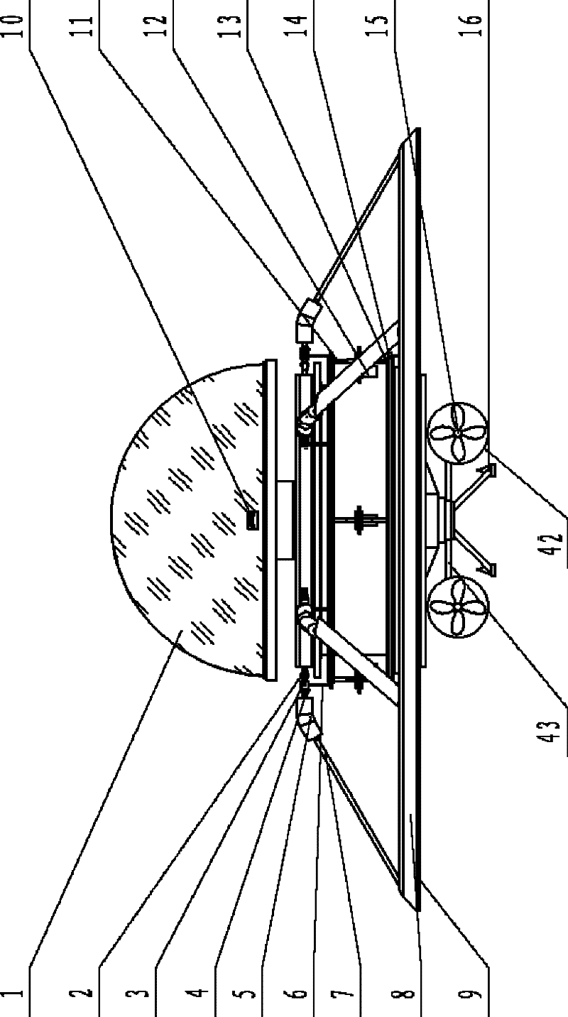
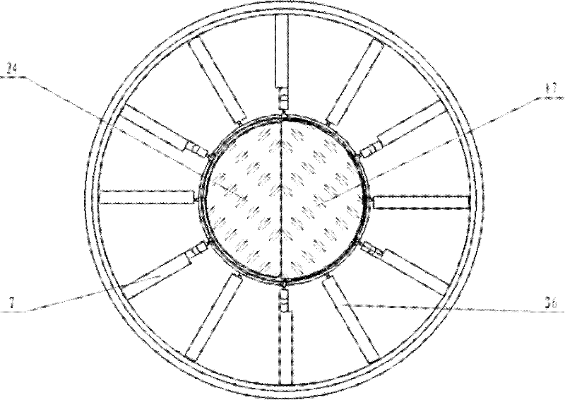
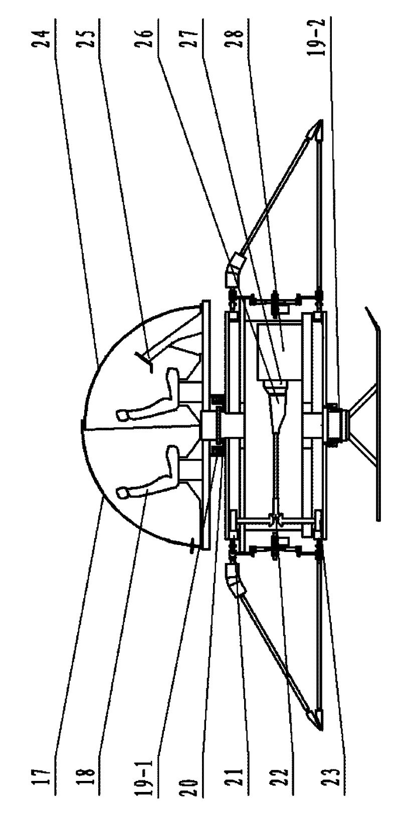
[0022] Such as figure 1 , figure 2 As shown, the saucer aircraft includes a cockpit 1, a fuselage, a torque conversion system, a rotor system, a transmission, a power system and a landing gear 16, and the fuselage is used as a fixed frame body of the overall structure of the aircraft, and the cockpit 1 is arranged on the fuselage top , the torque conversion system is driven by a servo motor 12, the servo motor 12 is connected to the gear transmission mechanism and the torque conversion hinge 4, one side of the torque conversion system is connected to the rotor system, and the rotor system is arranged on the outer edge of the fuselage, including the upper blade 7, the lower blade 36 and the propulsion paddle 15, the outer ends of the upper blade 7 and the lower blade 36 are respectively fixed by a fixed ring, the propulsion paddle 15 is arranged at the...


PUM


Abstract

The invention provides a disc type aircraft, which has the advantages of small volume, simple structure, high safety and strong applicability. The aircraft comprises a control cabin, an aircraft body, a variable torque system, a rotor wing system, a transmission device, a power system and an undercarriage. The aircraft body is of a fixed frame body of the aircraft integral structure. The control cabin is arranged above the aircraft body. The variable torque system is driven by a servo motor. The servo motor is connected to a gear transmission mechanism and a variable torque hinge. The rotor wing system is connected at one side of the variable torque system. The rotor wing system is arranged on the outer edge of the aircraft body and comprises an upper paddle, a lower paddle and a propelling paddle. The outer ends of the upper paddle and the lower paddle are respectively fixed through a fixed ring. The propelling paddle is arranged at the bottom of the aircraft body and connected to a motor for driving the propelling paddle. A gear ring is arranged at the other side of the variable torque system. The gear ring is matched with the transmission device in the form of a gear. The power input shaft of the transmission device is connected with the power system. The power system is composed of a gearbox, a clutch and an engine and arranged in an aircraft body cabin. The undercarriage is fixed at the bottom of the aircraft body.

Description

technical field [0001] The invention belongs to the technical field of aviation aircraft, in particular to a saucer aircraft. Background technique [0002] There are many types of existing helicopters, which can be used in tourism viewing, aerial photography, geological survey, high-voltage transmission line inspection, oil field pipeline inspection, highway management, forest fire prevention inspection, poisonous gas exploration, anti-drug, emergency lighting, and temporary communication In terms of platform, emergency rescue, ambulance and many other aspects, each helicopter is basically composed of thousands of parts. Difficult; there are many parts, the reliability of the parts themselves and the transmission mechanism will become worse, resulting in a high accident rate of the helicopter, threatening the life and property safety of the crew; due to the complexity of its structure, when the helicopter fails to detect and maintain It is also difficult. In addition, due ...

Claims


Application Information

Patent Timeline
IPC IPC(8): B64C39/06B64C11/44
Inventor 林文强李清良
Owner NORTHEASTERN UNIV
Learn More