Stamp-pad ink sponge assembly as well as seal assembly and stamping machine applying stamp-pad ink sponge assembly

A technology of stamping machine and ink, applied in printing, stamping and other directions, can solve the problems of uneven ink, difficult process, large flow, etc., and achieve the effect of uniform oil replenishment, uniform pressure balance, and clear and uniform stamping.

Pending Publication Date: 2018-11-06
CHANGZHOU HANS & WILSON ELECTRONICS TECH
View PDF15 Cites 2 Cited by
  • Summary
  • Abstract
  • Description
  • Claims
  • Application Information

AI Technical Summary

Problems solved by technology

[0002] At present, in the prior art, the printing ink is replenished to the printing ink sponge, and the purpose of uniform printing oil is generally achieved through multiple transfers (the printing oil is not directly transferred to the seal after being added to the printing ink sponge, but transferred from another section) On the ink sponge, so as to accelerate the diffusion), of course, there are also technologies that refuel through the pores, but the ink flowing out of the pores is often uneven, for example, the flow rate of the holes near the inlet is large, and the flow far away from the inlet is small, or the pore size near the inlet is smaller. to make the flow balance, but after all, it is impossible to maintain a stable flow balance, or the process is too difficult

Method used


Image

  • Stamp-pad ink sponge assembly as well as seal assembly and stamping machine applying stamp-pad ink sponge assembly
  • Stamp-pad ink sponge assembly as well as seal assembly and stamping machine applying stamp-pad ink sponge assembly
  • Stamp-pad ink sponge assembly as well as seal assembly and stamping machine applying stamp-pad ink sponge assembly

Examples


Embodiment 1

[0038] Such as figure 1 , 3 As shown, a printing ink sponge assembly, which is used on the stamping machine, it includes:

[0039] cavity 11;

[0040] Printing ink sponge 12, described printing ink sponge 12 is supported on the cavity 11;

[0041]The ink replenishment assembly for replenishing ink to the ink sponge 12 in the cavity 11, the ink replenishment assembly includes a hose 13 for conveying ink, and the hose 13 has an output pipe section 131 arranged in the cavity 11. There is a critical pressure in the ink passage for conveying ink in the output pipe section 131, and there is at least one set on the outlet pipe section 131 that communicates with the ink passage and is in a closed state and in the ink passage when the pressure in the ink passage is less than the critical pressure. When the pressure is greater than or equal to the critical pressure, the hole 1311 is in an open state, thereby replenishing ink to the ink sponge 12 .

[0042] In this embodiment, at lea...

Embodiment 2

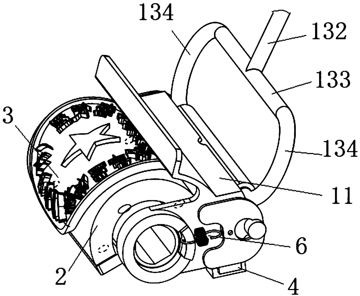
[0049] Such as figure 2 , 3 As shown, a stamp assembly, which includes:

[0050] A stamp holder 2 that can be driven to rotate;

[0051] A stamp 3 mounted on the stamp holder 2;

[0052] The printing ink sponge assembly in the first embodiment, the printing ink sponge assembly also includes the printing ink sponge support 14, the printing ink sponge support 14 is installed on the stamp support 2, the cavity 11 is installed on the printing ink sponge support 14, and the stamp support 2 rotates During the process, at least a part of the ink sponge 12 is in contact with the stamp 3, so that the ink sponge 12 provides ink to the stamp.

[0053] Such as image 3 As shown, a limit mechanism is provided between the cavity 11 and the ink sponge support 14, so that during the rotation of the stamp support 2, the limit mechanism makes the non-protruding parts of the ink sponge 12 and the stamp 3 Partially out of contact with and making the ink sponge 12 in contact with the raised ...

Embodiment 3

[0060] Such as Figure 4 As shown, a stamping machine, it includes:

[0061] The stamp shaft 5 driven to rotate;

[0062] In the stamp assembly in the second embodiment, the stamp support 2 in the stamp assembly is installed on the stamp shaft 5, and the stamp support 2 is driven to rotate by driving the stamp shaft 5 to rotate.

[0063] When the paper enters the stamping machine, the paper-feeding stepping motor 10 drives the rubber roller 20 to rotate, and the paper enters the meshing part of the rubber roller 20, and continues to feed the paper. When the paper reaches the designated stamping position, the stamp stepping motor 30 drives the stamp shaft 5 to rotate , the stamp shaft 5 will drive the stamp 3 to rotate once. During this one-round rotation, the stamp 3 will mesh with the ink sponge 12 once, and the ink will be transferred to the surface of the raised part of the stamp 3 when meshing, and then the stamp 3 will mesh with the paper. The ink is transferred from th...


PUM


Abstract

The invention discloses a stamp-pad ink sponge assembly as well as a seal assembly and a stamping machine applying the stamp-pad ink sponge assembly. The stamp-pad ink sponge assembly is used on the sealing machine and comprises a cavity, stamp-pad ink sponge, and a stamp-pad ink supplementary assembly for supplementing stamp-pad ink for the stamp-pad ink sponge in the cavity; the stamp-pad ink sponge is supported on the cavity; the stamp-pad ink supplementary assembly comprises a hose for conveying stamp-pad ink; the hose is provided with an output pipe section in the cavity; a stamp-pad inkchannel for conveying stamp-pad ink in the output pipe section has a critical pressure; at least one pore channel is arranged on the output pipe section, communicates with the stamp-pad ink channel, is in a closed state when the pressure in the stamp-pad ink channel is smaller than the critical pressure, and is in an opening state when the pressure in the stamp-pad ink channel is equal to or greater than the critical pressure to supplement stamp-pad ink for the stamp-pad ink sponge. The stamp-pad ink sponge assembly can uniformly add stamp-pad ink for the stamp-pad ink sponge to enable the stamping machine to stamp clearly and uniformly.

Description

technical field [0001] The invention relates to a printing ink sponge component, a stamp component and a stamping machine using the same. Background technique [0002] At present, in the prior art, the printing ink is replenished to the printing ink sponge, and the purpose of uniform printing oil is generally achieved through multiple transfers (the printing oil is not directly transferred to the seal after being added to the printing ink sponge, but transferred from another section) On the ink sponge, so as to accelerate the diffusion), of course, there are also technologies that refuel through the pores, but the ink flowing out of the pores is often uneven, for example, the flow rate of the holes near the inlet is large, and the flow far away from the inlet is small, or the pore size near the inlet is smaller. To make the flow balance, but after all, it is impossible to maintain a stable flow balance, or the process is too difficult. Contents of the invention [0003] T...

Claims


Application Information

Patent Timeline
Patent Type & Authority Applications(China)
IPC IPC(8): B41K3/14B41K3/62B41K3/54B41K3/60
CPCB41K3/14B41K3/54B41K3/60B41K3/62
Inventor 杨蕴震
Owner CHANGZHOU HANS & WILSON ELECTRONICS TECH
Why Eureka
Try Eureka