Lock clamping device

A technology of locking clips and clamping parts, which is applied in the field of workpiece processing, can solve the problems of non-adjustable rotation orientation, cumbersome and complicated fixed mode, and affect processing efficiency, and achieve the effects of simple structure, reduced operation steps, and improved processing efficiency

Inactive Publication Date: 2018-11-06
傅熠成
View PDF4 Cites 0 Cited by
  • Summary
  • Abstract
  • Description
  • Claims
  • Application Information

AI Technical Summary

Problems solved by technology

[0002] In modern industrial production, it is often necessary to fix some cylindrical workpieces and perform drilling operations. However, traditional workpiece processing devices generally fix the processed workpieces by bolt fastening. The fixing mode is cumbersome and difficult. At the same time, since the rotation position cannot be adjusted after being fixed, it is difficult to drill holes in the circumferential direction of the workpiece, which seriously affects the processing efficiency

Method used


Image

  • Lock clamping device
  • Lock clamping device
  • Lock clamping device

Examples


Embodiment Construction

[0025] All features disclosed in this specification, or steps in all methods or processes disclosed, may be combined in any manner, except for mutually exclusive features and / or steps.

[0026] Any feature disclosed in this specification (including any appended claims, abstract and drawings), unless expressly stated otherwise, may be replaced by alternative features which are equivalent or serve a similar purpose. That is, unless expressly stated otherwise, each feature is one example only of a series of equivalent or similar features.

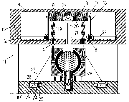
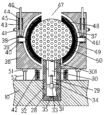
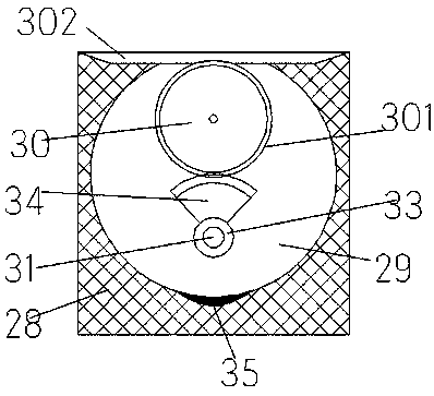
[0027] Such as Figure 1-5As shown, a lock clip device of the device of the present invention includes a base plate 10 and a crossbeam 12 fixedly arranged above the base plate 10 through a column 11, and the top end surface of the base plate 10 is provided with a placement groove with an upward opening. An upwardly extending placement column 28 is fixedly installed in the placement groove, and a recessed groove 302 with an upward opening is p...


PUM


Abstract

The invention discloses a lock clamping device. The lock clamping device comprises a bottom plate and a cross beam; the cross beam is fixedly arranged above the bottom plate through upright columns; aplacing groove with a through opening upwards is formed in the end surface of the top of the bottom plate; a placing column stretching upwards is fixedly arranged in the placing groove; a concave groove with a through opening upwards is formed in the end surface of the top of the placing column; workpieces are rotationally installed in the concave groove; the inner bottom wall of the concave groove stretches downwards to form a first rotating cavity; a first steering shaft is rotationally arranged in the first rotating cavity; the right side end of the steering shaft is rotationally arrangedin the inner wall of the right side of the first rotating cavity; the left side end of the steering shaft is in power connection with a first motor; the first motor is fixedly arranged in the inner wall of the left side of the first rotating cavity; a steering wheel is fixedly arranged on the first steering shaft; and a fan-shaped conductive tooth is fixedly arranged on the excircle of the steering wheel.

Description

technical field [0001] The invention relates to the technical field of workpiece processing, in particular to a locking clip device. Background technique [0002] In modern industrial production, it is often necessary to fix some cylindrical workpieces and perform drilling operations. However, traditional workpiece processing devices generally fix the processed workpieces by bolt fastening. The fixing mode is cumbersome and difficult. At the same time, since the rotation direction cannot be adjusted after being fixed, it is difficult to drill holes in the circumferential direction of the workpiece, which seriously affects the processing efficiency. Contents of the invention [0003] Aiming at the deficiencies of the above technologies, the present invention proposes a clip locking device. [0004] A locking clip device of the device of the present invention comprises a bottom plate and a crossbeam fixed above the bottom plate through a column, the top end surface of the...

Claims


Application Information

Patent Timeline
IPC IPC(8): B23Q3/06B23B39/00
CPCB23Q3/06B23B39/00
Inventor 傅熠成
Owner 傅熠成
Why Eureka
Try Eureka