
A datum correction method for 3D laser cutting plate

A three-dimensional laser and correction method technology, applied in laser welding equipment, metal processing equipment, welding equipment, etc., can solve the problems of large point-finding error and low cutting accuracy, and achieve the effect of reducing deviation and improving cutting accuracy

Active Publication Date: 2021-10-26
广州广汽荻原模具冲压有限公司
View PDF8 Cites 0 Cited by
  • Summary
  • Abstract
  • Description
  • Claims
  • Application Information

AI Technical Summary

Problems solved by technology

[0009] 1. There is a certain amount of deviation between the actual plate hole position and the theoretical digital model (the hole position tolerance is usually required to be ±0.5mm, and the maximum tolerance of the relative distance between the two holes is ±1.0mm. If the hole position is out of tolerance, there will be a greater deviation ), as a benchmark, there will be a large deviation in the program, resulting in low cutting accuracy;
[0010] 2. There is a large error in finding a point on the shape of the actual plate, which will cause a large deviation in the program as a benchmark, resulting in low cutting accuracy

Method used


Image

  • A datum correction method for 3D laser cutting plate

Examples


Embodiment Construction

[0025] Below, the present invention will be further described in conjunction with the accompanying drawings and specific implementation methods. It should be noted that, under the premise of not conflicting, the various embodiments described below or the technical features can be combined arbitrarily to form new embodiments. .

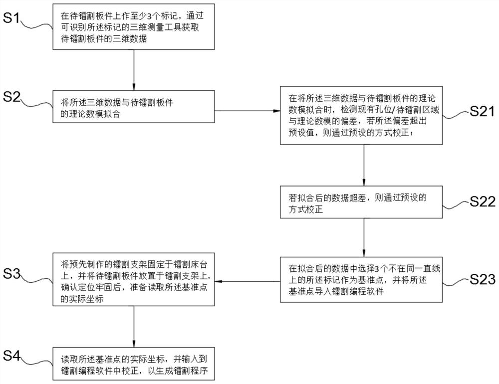
[0026] figure 1 As shown, it is a flow chart of a benchmark calibration method for a three-dimensional laser-cut plate according to a preferred embodiment of the present invention. The method includes the following steps:

[0027] S1. Make at least 3 marks on the board to be cut with radium, and obtain the three-dimensional data of the board to be cut with radium through a three-dimensional measurement tool that can identify the marks;

[0028] S2, combining the three-dimensional data with the theoretical numerical simulation of the board to be cut by radium;

[0029] S21. When combining the three-dimensional data with the theoretical numerical simu...


PUM


Abstract

The invention discloses a reference calibration method for a three-dimensional laser cutting plate, comprising the steps of: making at least three marks on the plate to be laser-cut, and obtaining the three-dimensional measurement of the plate to be laser-cut by a three-dimensional measuring tool that can identify the marks. Data: Combine the three-dimensional data with the theoretical numerical simulation of the plate to be cut by laser cutting, select 3 described marks that are not on the same straight line in the fitted data as reference points, and import the reference points into laser cutting Programming software; read the actual coordinates of the reference point, and input it into the laser cutting programming software for correction to generate a laser cutting program. Compared with finding the center of the circle in the existing hole position or finding the point on the shape, the method can find the reference point more efficiently and accurately, and can relatively accurately perform coordinate correction in the program to reduce the deviation and improve the cutting precision.

Description

technical field [0001] The invention relates to a three-dimensional laser cutting technology, in particular to a benchmark correction method for a three-dimensional laser cutting plate. Background technique [0002] Three-dimensional laser cutting technology is widely used in the production of automobile panels, and is mainly used to replace trimming and punching molds to cut the edge lines and holes of plate parts. At present, the three-dimensional laser cutting data is to directly use the product digital model as the cutting data, supplemented by the plate sensor with the laser head and the compensation function of the machine to laser cut the plate. The process is as follows: [0003] 1. Make a radium cutting bracket that conforms to the cut plate (usually cut with waste radium or welded with angle iron and supplemented with resin symbols), and fix it on the machine tool; [0004] 2. Import the theoretical digital model (including surface, line and hole) of the plate to ...

Claims


Application Information

Patent Timeline
Patent Type & Authority Patents(China)
IPC IPC(8): B23K26/38B23K26/70
CPCB23K26/38B23K26/70B23K26/702
Inventor 韦煜维郑雪妙梁晶晶曾铖段文博蔡健
Owner 广州广汽荻原模具冲压有限公司
Learn More