Testing device and testing method for restoring contaminated soil based on magnetism-electricity combination
A technology of combined restoration of contaminated soil, applied in the field of environmental geotechnical engineering, to achieve the effect of improving restoration efficiency
- Summary
- Abstract
- Description
- Claims
- Application Information
AI Technical Summary
Problems solved by technology
Method used
Image
Examples
Embodiment 1
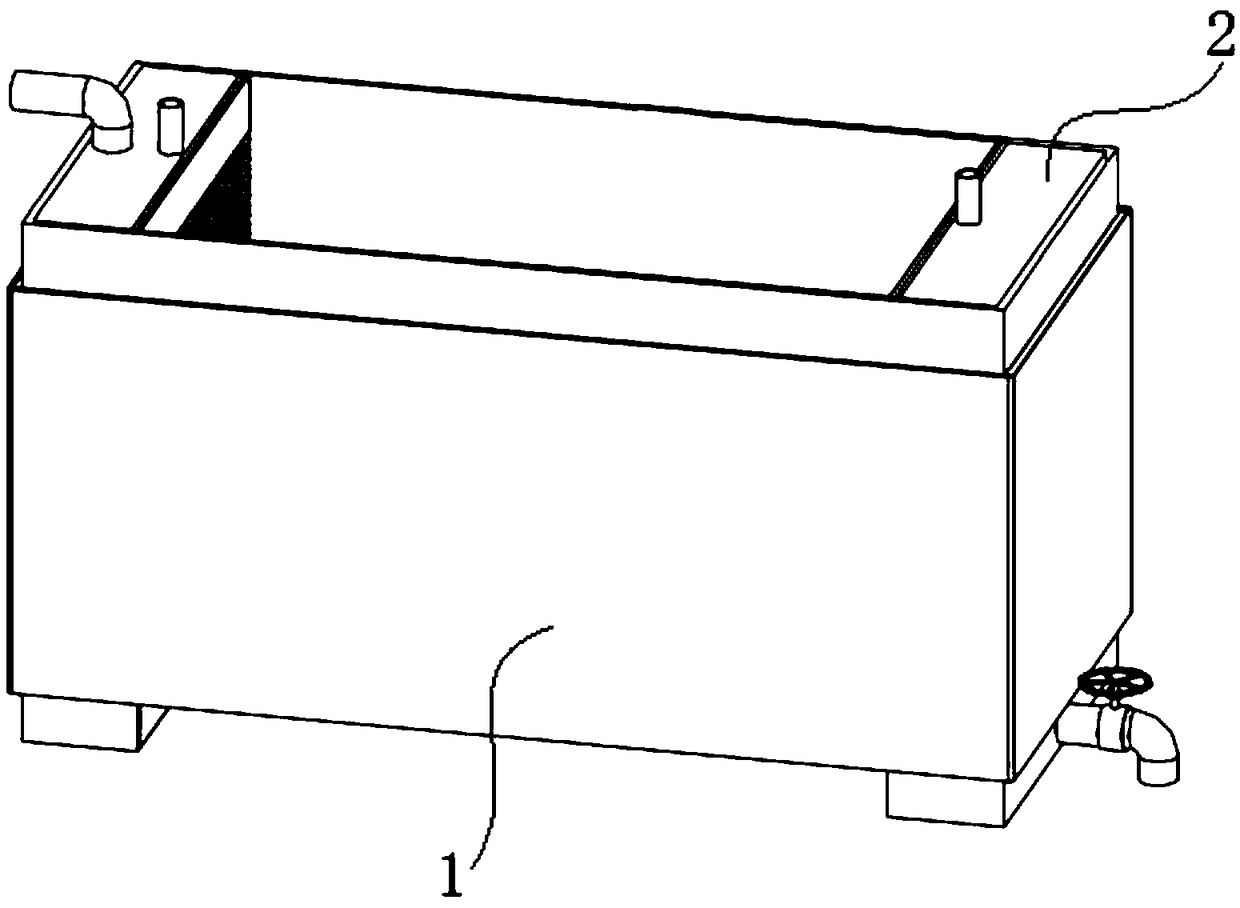
[0070] Such as figure 1 As shown, a test device based on magnetic-electric joint remediation of contaminated soil is characterized in that it includes system I1 and system II2.
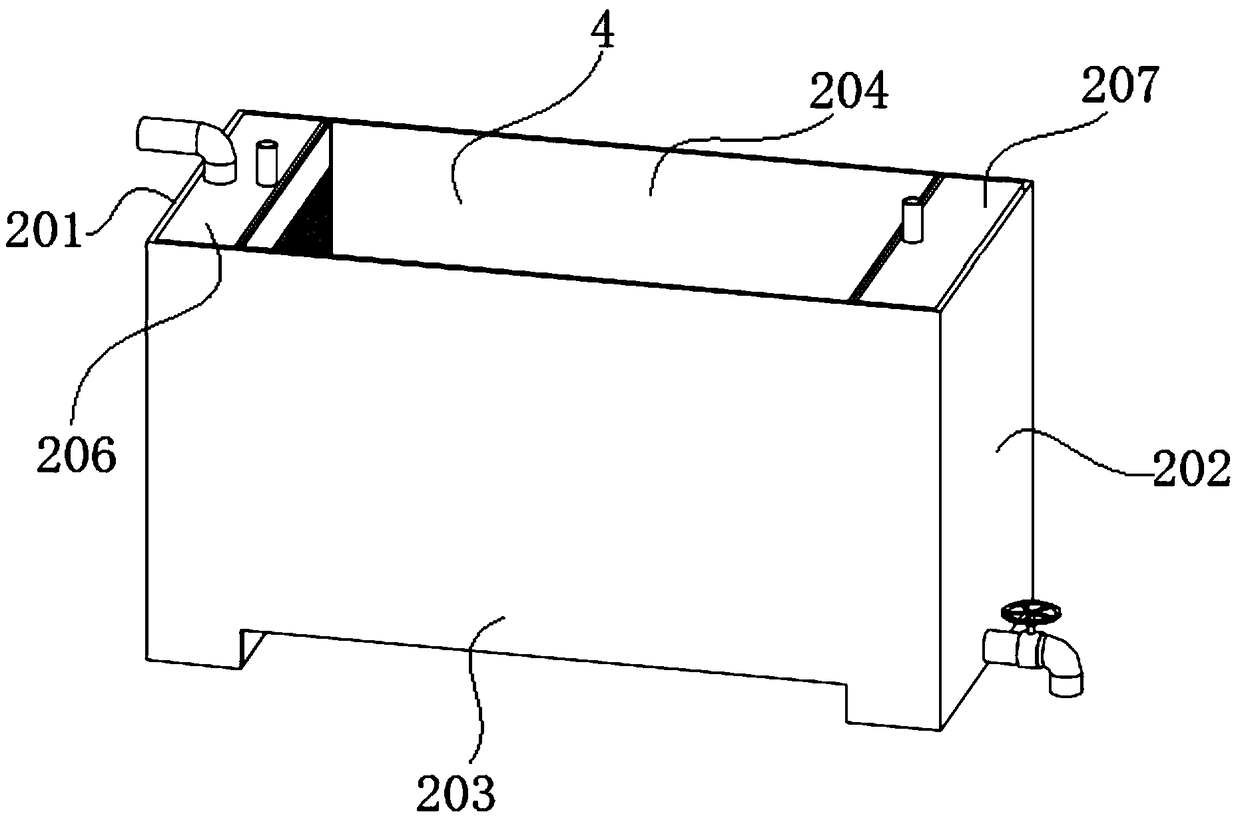
[0071] Such as figure 2 As shown, the whole of the system II2 is a hollow cuboid. The system II2 is composed of a left side plate 201, a right side plate 202, a front side plate 203, a rear side plate 204, a bottom plate 205, a top cover I206 and a top cover II207.
[0072] The system II2 includes the left side plate 201 , the circulation system I208 , the circulation system II209 and the right side plate 204 from left to right.
[0073] The circulation system I208 is composed of two porous plates I2081 and an anion selective membrane 2082. The anion selective membrane 2082 is located between two porous plates I2081. The two porous plates I2081 and the anion selective membrane 2082 are tightly pressed together and sealed around. The size of the circulation system I208 matches the size of the inn...
Embodiment 2
[0093] A test method based on magnetic-electric combined restoration of contaminated soil, characterized in that it comprises the following steps:
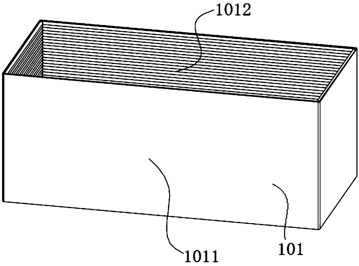
[0094] 1) Manufacture the anode chamber 3, the soil chamber 4 and the cathode chamber 5 in the system II2 according to the designed size, then wind the current-carrying wire 1012 in the system I1 on the outer wall of the system II2, and finally cover the current-carrying wire 1012 with an insulating shell 1011 .
[0095] The size of the soil chamber 4 is 15cm×9cm×9cm;
[0096] The dimensions of the anode chamber 3 and the cathode chamber 5 are 2cm×9cm×11cm;
[0097] The size of the insulating shell 1011 is 21cm×9cm×11cm.
[0098] 2) Connect the top cover I206 and the anode plate 301 together, and connect the top cover II207 and the cathode plate 501 together. Then put the integral structure formed by the top cover I206 and the anode plate 301 into the anode chamber 3, and put the integral structure formed by the top cover II207...
Embodiment 3
[0108] A test method based on magnetic-electric combined restoration of contaminated soil, characterized in that it comprises the following steps:
[0109] 1) Manufacture the anode chamber 3, the soil chamber 4 and the cathode chamber 5 in the system II2 according to the designed size, then wind the current-carrying wire 1012 in the system I1 on the outer wall of the system II2, and finally cover the current-carrying wire 1012 with an insulating shell 1011 .
[0110] The size of the soil chamber 4 is 15cm×9cm×9cm;
[0111] The dimensions of the anode chamber 3 and the cathode chamber 5 are 2cm×9cm×11cm;
[0112] The size of the insulating shell 1011 is 21cm×9cm×11cm.
[0113] 2) Connect the top cover I206 and the anode plate 301 together, and connect the top cover II207 and the cathode plate 501 together. Then put the integral structure formed by the top cover I206 and the anode plate 301 into the anode chamber 3, and put the integral structure formed by the top cover II207...
PUM
 Abstract
Description
Claims
Application Information
 - R&D Engineer
- R&D Manager
- IP Professional
- Industry Leading Data Capabilities
- Powerful AI technology
- Patent DNA Extraction
Browse by: Latest US Patents, China's latest patents, Technical Efficacy Thesaurus, Application Domain, Technology Topic, Popular Technical Reports.
© 2024 PatSnap. All rights reserved.Legal|Privacy policy|Modern Slavery Act Transparency Statement|Sitemap|About US| Contact US: help@patsnap.com


