
Allocation machine

A dispensing machine and workbench technology, applied in the direction of mixer, mixer accessories, dissolving, etc., to achieve the effect of high degree of automation and convenient distribution

Active Publication Date: 2018-11-06
WUHU KAIDE MACHINERY MFG
View PDF4 Cites 0 Cited by
  • Summary
  • Abstract
  • Description
  • Claims
  • Application Information

AI Technical Summary

Problems solved by technology

[0003] Now in order to solve the above-mentioned problem of accurately distributing water and other material powders, the present invention proposes a dispensing machine

Method used


Image

  • Allocation machine
  • Allocation machine

Examples


Embodiment Construction

[0015] In order to enable those skilled in the art to better understand the technical solutions of the present invention, the present invention will be described more clearly and completely below in conjunction with the accompanying drawings in the embodiments. Of course, the described embodiments are only a part of the present invention. Not all, based on this embodiment, other embodiments obtained by those skilled in the art without creative efforts are all within the protection scope of the present invention.

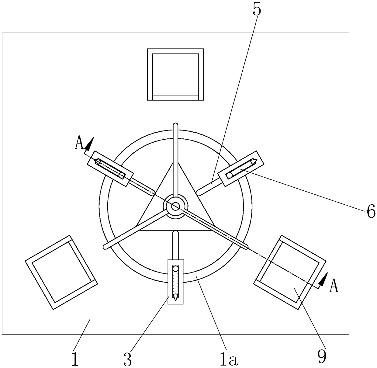
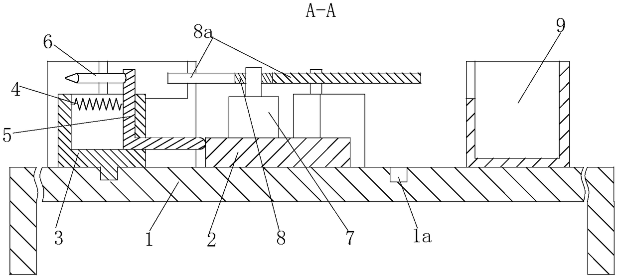
[0016] Such as Figure 1 to Figure 2 As shown, a dispensing machine includes a workbench 1, three bearing boxes 9 are fixedly installed on the workbench 1, an equilateral triangle auxiliary block 2 is fixedly installed in the center of the workbench 1, and a circular There are three sleeves 3 slidingly installed in the track groove 1a, and a spring 4 is fixedly installed inside each sleeve 3, and the springs 4 are connected with the auxiliary block 2 and are L-shaped...


PUM


Abstract

The invention relates to an allocation machine which comprises a working table, wherein three holding boxes are fixedly mounted on the working table; a regular triangular assisting block is fixedly mounted in the center of the working table; an annular track groove is formed in the working table; three sleeves are mounted inside the track groove in a sliding manner; a spring is fixedly mounted ineach sleeve; the springs are all connected with driving rods which are propped against the assisting block and take the shape of an L; spray guns are fixedly mounted on the driving rods; a motor is fixedly mounted in the center of the assisting block; central rings are respectively connected with shafts of the motor; three push rods matched with the driving rods correspondingly are welded with thecentral rings. The allocation machine is high in automation degree, with rotation of the push rods and cooperation with the driving rods, a plurality of spray guns can be not only driven to rotate tocarry out conveying, but also controlled to pause in specific positions stably, water and material powder can be automatically sprayed and conveyed, and allocation and conveying can be relatively conveniently carried out in a whole allocation process.

Description

technical field [0001] The invention relates to an auxiliary equipment for machining, in particular to a distribution machine. Background technique [0002] Generally speaking, in the manufacture of cement or concrete bricks, it is necessary to mix water and powder of some materials, and then stir. In reality, under the premise that the strength of the stirring equipment is small but the amount of stirring required is too large, it can be considered to divide water and powders of various materials into multiple components, and then each component is equipped with a stirring The equipment is used for stirring in order to achieve the effect of efficient and rapid stirring, but the problem is how to stably distribute water and other material powders to the corresponding positions, which has become a difficult problem for people to solve. Contents of the invention [0003] Now in order to solve the above-mentioned problem of accurately dispensing water and other material powd...

Claims


Application Information

Patent Timeline
Patent Type & Authority Applications(China)
IPC IPC(8): B01F15/02
CPCB01F35/716B01F35/7179B01F2101/28
Inventor 邢超陈邦军吴空涛
Owner WUHU KAIDE MACHINERY MFG
Learn More