Ventilation and air-changing device for factory buildings
A ventilation device and plant technology, applied in the direction of dry gas arrangement, gas treatment, combustion method, etc., can solve the problems of no reuse, tea dust dumping, etc., and achieve the effect of improving the use efficiency
- Summary
- Abstract
- Description
- Claims
- Application Information
AI Technical Summary
Problems solved by technology
Method used
Image
Examples
Embodiment 1
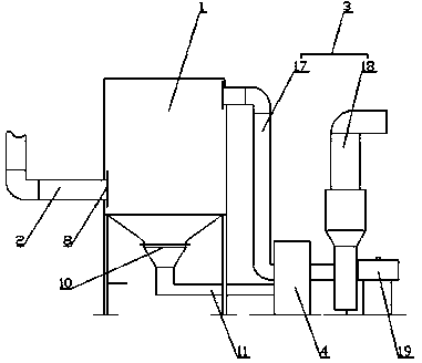
[0020] Such as figure 1 As shown, the factory building ventilation device includes a central dust collector 1, a heat preservation gas collection pipe 2, an air outlet pipe 3 and a combustion furnace 4. The air inlet 8 of the central dust collector 1 is connected to the heat preservation gas collection pipe 2, and the air outlet is connected to the The inlet of the pipeline 3 is connected, and the dust outlet 10 is connected to the feed port of the combustion furnace 4; the gas outlet pipeline 3 is located in the heating area of the combustion furnace 4, and the gas outlet pipeline 3 is connected to the drying and heating chamber in the factory building.
[0021] In this embodiment, the heat preservation and gas collection pipeline 2 is arranged above each device in the factory building, which is used to collect the tea generated during tea processing, the central dust collector 1 is used to separate the tea dust in the air, and the air outlet pipeline 3 is used to discharge...
Embodiment 2
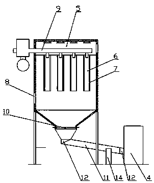
[0023] Such as figure 2 As shown, compared with Example 1, this embodiment optimizes the central dust collector 1. The central dust collector 1 includes a dust removal filter box 5, and a filter bag 6 is arranged in the dust removal filter box 5. The filter bag 6 is fixedly installed on the dust removal filter box through a skeleton 7 In the box 5, and vertically above the air inlet 8, the top of the filter bag 6 is open, and the pulse injection device 9 is arranged above the filter bag 6, and the suction port of the pulse injection device 9 and the filter bag The top openings of 6 are arranged oppositely in the vertical direction; the dust outlet 10 is arranged on the bottom of the dust filter box 5, and is connected with the feed port of the combustion furnace 4 through the feed pipe 11.
[0024] In this embodiment, since the central dust collector 1 is used for a long time, a large amount of dust will accumulate on the filter bag 6 in the dust filter box 5, which will affe...
Embodiment 3
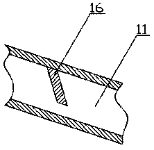
[0026] Such as figure 1 , 2 As shown, compared with embodiment 2, the present embodiment optimizes the material guide pipeline 11, the material guide pipeline 11 is arranged downwardly from the dust removal filter box 5 to the combustion furnace 4 places, and the material guide pipeline 11 is respectively connected with the elastic hose 12 The dust removal filter box 5 is connected with the combustion furnace 4, and a heat insulating layer is laid on the pipe wall of the material guide pipe 11.
[0027] In the present embodiment, the material guide pipe 11 is inclined downward from the dust removal filter box 5 to the combustion furnace 4, so that the collected tea dust can move downwards by gravity, so as to facilitate entering the combustion furnace 4, and guide The material pipeline 11 is respectively connected with the dust removal filter box 5 and the combustion furnace 4 through the elastic hose 12, and the elastic hose 12 enables the material guide pipeline 11 to move,...
PUM
 Abstract
Description
Claims
Application Information
 - R&D
- Intellectual Property
- Life Sciences
- Materials
- Tech Scout
- Unparalleled Data Quality
- Higher Quality Content
- 60% Fewer Hallucinations
Browse by: Latest US Patents, China's latest patents, Technical Efficacy Thesaurus, Application Domain, Technology Topic, Popular Technical Reports.
© 2025 PatSnap. All rights reserved.Legal|Privacy policy|Modern Slavery Act Transparency Statement|Sitemap|About US| Contact US: help@patsnap.com


