Multifunctional led dimming interface circuit

A dimming interface and multi-functional technology, which is applied in the field of multi-functional LED dimming interface circuit, can solve problems such as the limitation of flexibility in dimming mode of LED lighting devices, and achieve dimming schemes and flexible effects

Active Publication Date: 2020-08-21
TRIDONIC
View PDF6 Cites 0 Cited by
  • Summary
  • Abstract
  • Description
  • Claims
  • Application Information

AI Technical Summary

Problems solved by technology

[0004] In the prior art, in order to realize the above three dimming methods for the LED drive circuit, it is necessary to design different dimming circuits respectively. Correspondingly, after the dimming mode and the dimming circuit of the LED driving circuit are It can be connected with a dimmer corresponding to this dimming method, which brings great restrictions on the flexibility of LED lighting device dimming methods

Method used


Image

  • Multifunctional led dimming interface circuit
  • Multifunctional led dimming interface circuit
  • Multifunctional led dimming interface circuit

Examples


Embodiment Construction

[0032] The present invention will be further described in detail below with reference to the accompanying drawings and in combination with specific embodiments.

[0033] A multifunctional LED dimming interface circuit provided by an embodiment of the present invention includes: a dimming signal output module, a dimension control unit module, a dimmer interface module, the dimming signal output module is connected with a micro control unit module, and the micro control unit The module is connected with the dimmer interface module;

[0034] The dimmer interface module is connected to the LED dimmer, and the dimmer interface module receives the dimming operation signal sent by the dimmer and sends it to the micro control unit module;

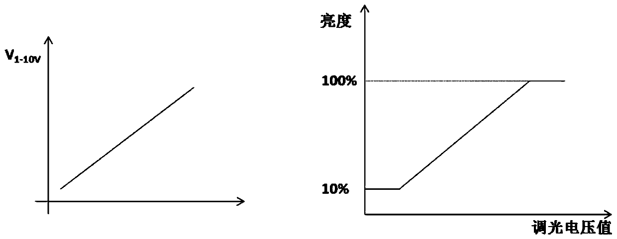
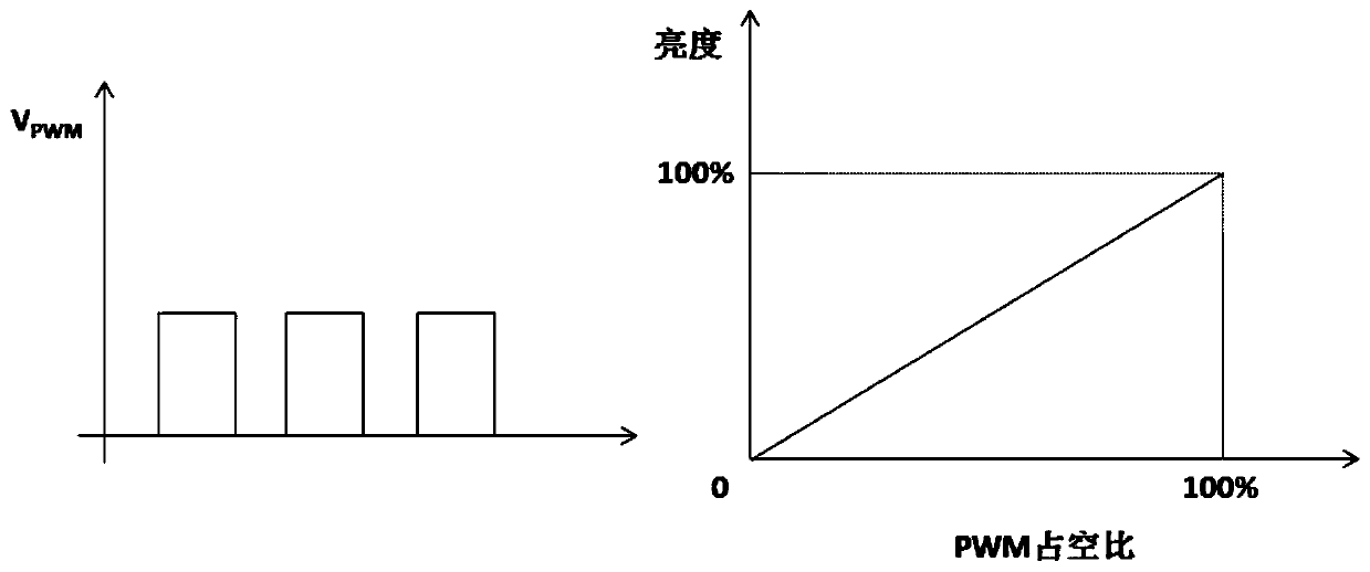
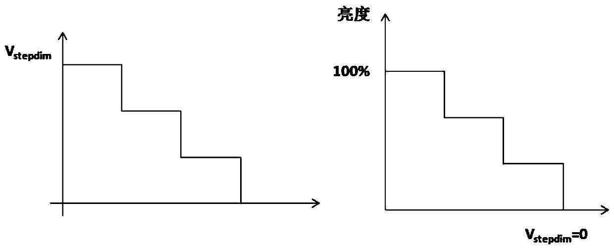
[0035] According to the dimming operation signal, the micro control unit module determines that the dimming mode corresponding to the dimmer is one of the various preset dimming modes in the micro control unit module, and the micro control unit mod...


PUM


Abstract

A multifunctional LED dimming interface circuit provided by the present invention includes: a dimming signal output module, a micro control unit module, a dimmer interface module, the dimming signal output module is connected to the micro control unit module, and the micro control unit module is connected to the dimmer The dimmer interface module, the dimmer interface module leads out a plurality of dimmer connection terminals, and the present invention realizes a dimmer interface circuit applicable to 1‑10V by automatically identifying the dimmer type connected to the dimmer interface At least two of the three dimming types, PWM dimming and step dimming, provide more flexible options for the dimming scheme of the LED lighting device and the selection of dimmers.

Description

technical field [0001] The invention relates to the technical field of LED driving, in particular to a multifunctional LED dimming interface circuit. Background technique [0002] LED lighting devices are energy-saving and environmentally friendly, and have a variety of flexible dimming methods, making lighting solutions more diverse and intelligent. As a new generation of lighting sources, they have been widely used. [0003] In the current LED dimming scheme, it is divided according to the change form of the voltage signal. The most commonly used three dimming methods are: 1-10V dimming, PWM (Pulse Width Modulation, pulse width modulation) dimming and StepDim step Dimming, such as figure 1 Voltage shown for 1-10V dimming (V 1-10V ) changes and the corresponding brightness changes, such as figure 2 Shown is the voltage for PWM dimming (V PWM ) changes and the corresponding brightness changes, such as image 3 Shown is the voltage for StepDim step dimming (V stepdim )...

Claims


Application Information

Patent Timeline
Patent Type & Authority Patents(China)
IPC IPC(8): H05B45/10H05B45/325H05B45/345H05B44/00
CPCH05B45/10
Inventor 钟国基毛秋翔
Owner TRIDONIC
Why Eureka
Try Eureka