Key structure

A button and component technology, applied in the field of button structure with a thin and light appearance, can solve the problems affecting the touch and feel of the button cap 21

Inactive Publication Date: 2018-11-02
PRIMAX ELECTRONICS LTD
View PDF5 Cites 0 Cited by
  • Summary
  • Abstract
  • Description
  • Claims
  • Application Information

AI Technical Summary

Problems solved by technology

[0008] However, since the metal trigger 23 is made of metal material, when the user presses the key cap 21...

Method used


Image

  • Key structure
  • Key structure
  • Key structure

Examples


Embodiment Construction

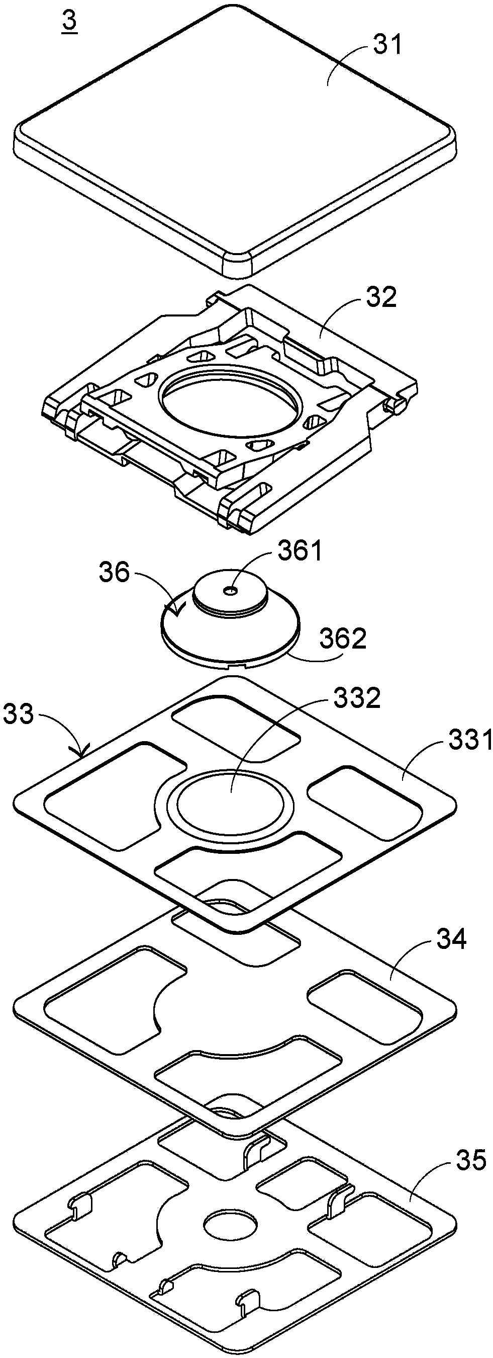
[0043] In view of the problems in the prior art, the present invention provides a button structure that can maintain a thin and light appearance and improve the touch feeling, and to solve the problems in the prior art. Please also see image 3 as well as Figure 4 , image 3 It is a structural exploded schematic diagram of the button structure of the present invention in the first preferred embodiment, and Figure 4 It is a schematic cross-sectional side view of the button structure of the present invention in the first preferred embodiment. The button structure 3 includes a button cap 31, a scissors-type connection element 32, a trigger assembly 33, a switch circuit board 34, a bottom plate 35 and an elastic element 36. The bottom plate 35 is connected to the scissors-type connection element 32, and its function is to carry the key cap 31, the scissors Type connection element 32, trigger assembly 33 and switch circuit board 34 on it. The switch circuit board 34 is dispos...


PUM


Abstract

The invention discloses a key structure, which comprises a key cap, a trigger component, a switch circuit board and an elastic component, wherein the trigger component is located on the switch circuitboard, and the elastic component is located between the key cap and the trigger component, which can push against the trigger component due to the moving key cap; and the elastic component is provided with a recessed portion, which is located on the top end of the elastic component and can deform due to pushing of the key cap to increase the distance the key cap moves. Therefore, the key structure of the present invention can improve the touch feeling of a user touching the key cap.

Description

technical field [0001] The invention relates to a key structure, in particular to a key structure with a light and thin appearance. Background technique [0002] Common computer peripheral input devices include a mouse, a keyboard, and a trackball. The keyboard can directly input text and symbols to the computer, so it is highly valued by users and input device manufacturers. Among them, the more common one is a keyboard that includes a scissor-type connecting element. [0003] Next, the architecture of the key structure in the keyboard including the scissor-type connection elements is described. see figure 1 , which is a schematic cross-sectional side view of an existing button structure. The existing button structure 1 includes a button cap 11, a scissors-type connecting element 12, an elastic rubber body 13, a membrane switch circuit 14 and a bottom plate 15, and the bottom plate 15 is used to carry the key cap 11, the scissors-type connecting element 12, the elastic r...

Claims


Application Information

Patent Timeline
IPC IPC(8): H01H13/7073H01H3/12
CPCH01H13/7073H01H3/125H01H2215/004
Inventor 陈柏安潘锦松
Owner PRIMAX ELECTRONICS LTD
Why Eureka
Try Eureka